I prefer the smaller wires like you suggest for input. I think I've used 24awg and 26awg. 28awg will be even smaller, perhaps difficult to work with.
I do like larger wire for speaker terminals inside the amp. 16awg is probably sufficient there, I might be using 14, can't remember. I just kinda go with whatever I have on hand that, I'm using for speaker cable.
This part is no joke: Every circuit has two,.... Nevermind, I won't be good at explaining it... If you have two small individual shielded conductors for your input, twist the Plus and Minus conductor together. If you have two wires inside another sheath, that's fine, if you have a coaxial type of RCA-wire, that's fine too. The point is just that the return path of the signal is as close as possible to the positive wire in that same circuit. You maybe already knew that about twisted pairs, but I somehow was slow to pick up on that.
thanks @alexqs for taking your time to explain this.
do you prefer the smaller size because it's less bulky and maybe easier for tight turns inside the housing or because of other (electrical ? ) properties?
no, i had no idea about the thing you explained regarding twisted pairs. so if i understand it right there's always the signal path and the return path. those two should be isolated from each other (well...obviously) but at the same time be as close to each other as possible. if this is achieved a) using the center conductor for signal, shield for return b) two individually insulated leads twisted together c) other construction of the same sort .... won't really matter as long as they run closely together.
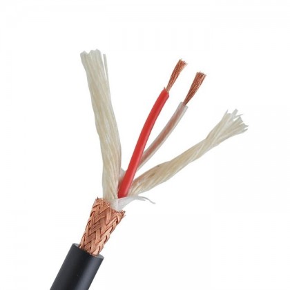
so i might as well use this kind (signal in the middle, shield for return):
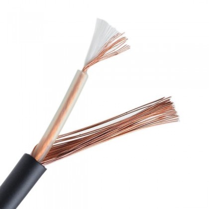
or this kind (one lead for signal, one for return)
...and there'll be no difference. also the gauge won't really matter. did i get that right?
.....why it is that the two leads have to run close to each other ... i'll save that question for another time. 😀
do you prefer the smaller size because it's less bulky and maybe easier for tight turns inside the housing or because of other (electrical ? ) properties?
no, i had no idea about the thing you explained regarding twisted pairs. so if i understand it right there's always the signal path and the return path. those two should be isolated from each other (well...obviously) but at the same time be as close to each other as possible. if this is achieved a) using the center conductor for signal, shield for return b) two individually insulated leads twisted together c) other construction of the same sort .... won't really matter as long as they run closely together.
so i might as well use this kind (signal in the middle, shield for return):
or this kind (one lead for signal, one for return)
...and there'll be no difference. also the gauge won't really matter. did i get that right?
.....why it is that the two leads have to run close to each other ... i'll save that question for another time. 😀
I'm at a loss to explain the science behind it, because I'm not an electrical engineer. My limited understanding has something to do with the wire being able to transmit the (small / line-level) signal quickly. You don't want the wire to be so large that it can store energy like a capacitor. As a side note, I know someone who purchased a lot of high-end gear right after his parents past. Call it a mid life crisis if you will, but I have personally spent a lot of time listening to equipment that had 1-meter interconnects between the amp and pre-amp which cost about a thousand US dollars, along with speaker cables that were several thousand dollars. The overall system of DAC, Preamp, Amp, Speakers, etc was well over tens of thousands of dollars. Did it sound awesome, Of course! Can I tell the difference between it and my current system that I have invested less than two grand into (maybe only 1500), a few hundred dollars at a time, whilst enjoying the education and building over the last five years? -Actually I think my system sounds better, wider and deeper sound stage, and more resolution of the placement of instruments within the sound stage.thanks @alexqs for taking your time to explain this.
do you prefer the smaller size because it's less bulky and maybe easier for tight turns inside the housing or because of other (electrical ? ) properties?
If consumers really understood the science behind all of it, and understood that while sometimes you may find minuscule measurable improvements; they would have to ask themselves if that difference (which may not even be audible to the human ear) is really worth $250 / foot!
Still I think there is something to the science of not using large diameter cable for the line-level inputs.
I do like science. I think the technical design of a circuit is much more important than the type of shield a wire has. I can clearly hear a significant difference between single-ended and balanced inputs for example, so that seemed a worthwhile expense in my design goal. Debating in my mind over which kind of wire to use can be fun, but (in my experience) the difference is small.
Yes, you got it!no, i had no idea about the thing you explained regarding twisted pairs. so if i understand it right there's always the signal path and the return path. those two should be isolated from each other (well...obviously) but at the same time be as close to each other as possible. if this is achieved a) using the center conductor for signal, shield for return b) two individually insulated leads twisted together c) other construction of the same sort .... won't really matter as long as they run closely together.
Looks fine.so i might as well use this kind (signal in the middle, shield for return):
I'm sure that would work too, although you may not need the braided shield on the outside. You'll end up either stripping the braided shield off at the end, or the time consuming task of un-braiding it (toothpic and magnifying glass), then joining it together with the ground inside the cable. You only need two, not three wires for RCA.or this kind (one lead for signal, one for return)
My opinion is that smaller is better. I say this with the realization that it's possible that you or I may not even be able to hear the difference....and there'll be no difference. also the gauge won't really matter. did i get that right?
I'll let someone who can explain it better answer that. AndrewT taught that one to me......why it is that the two leads have to run close to each other ... i'll save that question for another time. 😀
p.s. Hoping I haven't re-opened the can of worms about special wires. I think the point is simply:
Will this wire "work well" with LM3886 Done Right. -The simple answer is "Yes"
Last edited:
many thanks for all your advice ... i learned a lot!
i'll order some cables for this project and make a mental note to have a closer look at the whole cable thing at a later stage ..... 🙂
i'll order some cables for this project and make a mental note to have a closer look at the whole cable thing at a later stage ..... 🙂
many thanks for all your advice ... i learned a lot!
i'll order some cables for this project and make a mental note to have a closer look at the whole cable thing at a later stage ..... 🙂
No need to order from across the ocean:
https://www.conrad.at/de/audiokabel-1-x-022-mm-schwarz-bkl-electronic-1509008-meterware-457893.html
Thanks, ghk!
I am planing on using an alps rk27 pot with this amp and I'm not sure how to solder the cables to those tiny pins. Do most people use a pcb for the pot or are they just better at soldering? 🙂
can anyone recommend a pcb for the rk27?
thanks!
I am planing on using an alps rk27 pot with this amp and I'm not sure how to solder the cables to those tiny pins. Do most people use a pcb for the pot or are they just better at soldering? 🙂
can anyone recommend a pcb for the rk27?
thanks!
With an analog interconnect, there are no electrical reason for larger conductors. But there are mechanical reasons, in a portable cable anything smaller than 26AWG is rather fragile and could break.careful with the jokes. my electronics knowledge is very limited and i might mistake it for serious advice 🙂.
will a 26 or 28 awg lead be ok for internal wiring between rca plug, pot and amp?
At audio frequencies, electricity in cables just doesn't work that way. Small cable or large cable, no differences. Now at radio frequencies, things get real complicated, real fast.I'm at a loss to explain the science behind it, because I'm not an electrical engineer. My limited understanding has something to do with the wire being able to transmit the (small / line-level) signal quickly. You don't want the wire to be so large that it can store energy like a capacitor.
I'll let someone who can explain it better answer that. AndrewT taught that one to me.
p.s. Hoping I haven't re-opened the can of worms about special wires. I think the point is simply:
Will this wire "work well" with LM3886 Done Right. -The simple answer is "Yes"
Well, yeah sorta-kinda. While I do agree with your fundamental notion that cables at RF are a different ball of wax than cables at DC (which from an RF perspective includes audio frequencies), the notion that the cables change their behaviour is inaccurate.
Cables do have a capacitance from the centre conductor to the shield, a leakage conductance from the centre to the shield, a series resistance, and a series inductance.
If the wavelength of the signal being conducted is very long compared to the length of the cable, the lumped parameter model (R-L-C-G) is accurate. If the wavelength of the signal is short compared to the cable, a model that includes the characteristic impedance of the cable (Z0) along with parameters such as the dielectric loss (S-parameter model) is more applicable.
That said, the idea that the energy sloshes in and out of a short interconnect cable at audio frequencies and that this is somehow an issue is misguided at best. The cable will present a capacitive load on the cable driver. For a common 1-2 m cable, the cable is responsible for maybe 100 pF (= 80 kΩ reactance @ 20 kHz). This is not a cause for concern.
Tom
There are tons of RK27 compatible PCBs on eBay. Pick one. Alternatively, solder the wire to the pins of the pot and zip tie them together (and to the chassis or the pot) to provide strain relief on the pot connections.
Tom
Tom
The most convenient and mechanically stable way is to use a dedicated PCB, IMO. 'bay is full of PCBs for RK27 pots and there are a couple of designs to select from. I can also offer my PCBs (see here). I made them for myself because I didn't like PCBs from the far East due to their bigger than necessary size and common ground for both channels.
I can also offer my PCBs (see here). I made them for myself because I didn't like PCBs from the far East due to their bigger than necessary size and common ground for both channels.
Cool! There you go. For the next rev., I suggest flooding the grounds like you did on the RK097 board. That aside, nice and simple PCB. Excellent.
Shipping one of those from Germany to Mixi in Austria shouldn't break the bank either.
Tom
Thanks for the complement, Tom!
If next version will even be made I'll use more copper for the GNDs🙂
If next version will even be made I'll use more copper for the GNDs🙂
Thanks, Oleg and Tom! This looks great!
Also the pcb for block transformers is just what i've been looking for for another project. I'll be in touch via pm!
This makes me very happy!
Also the pcb for block transformers is just what i've been looking for for another project. I'll be in touch via pm!
This makes me very happy!
Do keep in your mind that each channel has a TWO wire input and a TWO wire output.Thanks, ghk!
I am planing on using an alps rk27 pot with this amp and I'm not sure how to solder the cables to those tiny pins. Do most people use a pcb for the pot or are they just better at soldering? 🙂
can anyone recommend a pcb for the rk27?
thanks!
Thus a stereo vol pot has 4 PAIRs of signal wiring.
Do not connect any of those signal wires to power ground.
If there are any metal casing parts in the construction of the vol pot then connect these to the enclosure.
Thanks, Andrew.
I already knew which pins to use for signal and which for gnd. It's more an issue of not knowing how to solder tiny wires to tiny pins 🙂
I think most of the RK27 is made of plastic except for the turning spindle which will be mounted to the enclosure anyways. Is that the right thing to do or did I miss your point ?
OK.
You may need to earth the metal spindle to the enclosure.
There was a very recent Thread discussing this.
You may need to earth the metal spindle to the enclosure.
There was a very recent Thread discussing this.
Thanks, Andrew.
I already knew which pins to use for signal and which for gnd. It's more an issue of not knowing how to solder tiny wires to tiny pins 🙂
I think most of the RK27 is made of plastic except for the turning spindle which will be mounted to the enclosure anyways. Is that the right thing to do or did I miss your point ?
Whenever I solder wires to parts, I find that if I tin the wire a little bit in the end before I begin; then when I go to solder the wire to a pin that everything seems to heat/flow/bond quicker.
- Home
- Amplifiers
- Chip Amps
- Neurochrome LM3886DR Build