If I am using four 12V (fully load 13,3V) batteries in series as "power supply" will I have to switch all 3 wires with an SSR or only "+ and -"?
Found an SSR from Panasonic. May be better than no-name-Ebay.
Found an SSR from Panasonic. May be better than no-name-Ebay.
I see the cup is blue instead of red...
Yeah... It's my one personality flaw. I've always preferred blue & white. Much to the locals' dismay. 🙂
I happened to have heard both this little guy, and one of Tom’s personal Modulus86 (4 channel for his LX Mini, IIRC?) in my home system before the cited event.
Yep. That 4xMOD86 is still driving my LXmini speakers.
Tom please feel free to rebut, but as much as the DR was at least the equal to any number of similarly powered commercial products or DIY chippers I’ve heard in my sordid career, the Modulus was something pretty darned special.
That's what I remember as well. The LM3886DR is every bit as good as any good LM3886 implementation. The trick is to find a good implementation as there are many ways to muck it up.
The LM3886DR (and a few other amps) did get some playing time at the DIY meet, but folks quickly requested the MOD86 to be hooked back up. 🙂
I’d always been of the opinion that past a certain point “vanishing / immeasurably low” distortion was just an exercise in specmanship, but there is something going on with that piece that either is, or is not, directly related.
My suspicion is that people have been so focused on the THD at 1 kHz that they've lost track of everything else. The THD of the LM3886 does rise above audible both at the low end and the high end. Some may prefer the higher THD at LF as it creates a bit of a warmer sound due to harmonic extension. Others (including me) find it to be slightly muddy. In the high end, there's almost universal agreement that the chip amps, including the LM3886, sound a little strained, harsh, or "like a chipamp". That I think is because the rising THD vs frequency of the LM3886.
The Modulus-86 uses error correction to reduce the THD (and a wide array of other parameters) to levels well below audible at all frequencies.
That said, the LM3886DR wrings as much performance out of the LM3886 as possible. It actually beats the data sheet specs on a few parameters (THD, for example) thanks in part to the better components we have available now versus when the data for the data sheet curves were taken.
Tom
If I am using four 12V (fully load 13,3V) batteries in series as "power supply" will I have to switch all 3 wires with an SSR or only "+ and -"?
Yep. There's no need to switch the ground. Just switch V+ and V-.
Found an SSR from Panasonic.
May be better than no-name-Ebay.
I'd say definitely better than a no-name from ePay.
Double-check with the data sheet that the SSR you've chosen is suitable for switching DC. Also note that some SSRs have zero-detection and require the switched voltage to be near zero before they'll switch. That'll work great for AC, which crosses 0 V twice every cycle, but not for DC.
You could also make your own SSR by using a pair of power MOSFETs and a floating photovoltaic gate driver.
Tom
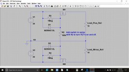
Something like this could be workable. Switching R2 into circuit enables both FET's (together) and opening the connection turns them both off. The zeners ensure that Vgs is never exceeded.
The switch in series with R2 could even be replaced by an opto enabling remote control of the PSU.
(Its just a quick doodle and not intended as a fully worked optimised example).
The switch in series with R2 could even be replaced by an opto enabling remote control of the PSU.
(Its just a quick doodle and not intended as a fully worked optimised example).
Attachments
Tom, once again - sorry for how this season started out for you, but it’s great to have you back. I’m borrowing this from a source that doesn’t apply here, but - one day at a time.
Thank you.
So because of the rising THD vs. frequency of the LM3886 may be the best could be to use them for midrange in an active 2.1 or 3-way active system. (if someone wants to spare some $ not using the Mod86 for all ways)
So because of the rising THD vs. frequency of the LM3886 may be the best could be to use them for midrange in an active 2.1 or 3-way active system. (if someone wants to spare some $ not using the Mod86 for all ways)
In case if the batteries/voltage go down ( not enough sun) I want to add a PSU/charger. Is it better to use one with about 52-56VDC or better two with about 26-28VDC in series or one with +/- 26-28V? May be I want to listen to music while loading.
Again thanks for your help.
Again thanks for your help.
I'd probably aim for ±28 V. That said, battery management is not my area of expertise so to say anything more useful than that, I'd have to read up on it.
Tom
Tom
Is it possible by changing the coil to lower the noise (mid horn running only up to 1kHz/18-24dB/oct)?
About115dB/1W is a lot and together with a DSP it is a bit noisy.
About115dB/1W is a lot and together with a DSP it is a bit noisy.
Put a shorting plug on the input of the amp. If the noise level drops to an acceptable level (preferably well below audible at the listening position), messing with the amp won't change anything. You'll have to get a quieter DSP.
Messing with the output inductor will not change the noise level of the LM3886DR. You might be able to lower the noise a bit by messing with the feedback networks around the LM3886. Ensuring stability across the entire signal swing while doing that is a challenge, however.
Tom
Messing with the output inductor will not change the noise level of the LM3886DR. You might be able to lower the noise a bit by messing with the feedback networks around the LM3886. Ensuring stability across the entire signal swing while doing that is a challenge, however.
Tom
Last edited:
rsqt,
The output inductor is part of the RL network to help assure the amp's stability with odd loads. It is not a noise filter.
The output inductor is part of the RL network to help assure the amp's stability with odd loads. It is not a noise filter.
Cool! Let's see if we can get closer to 100%.
You may find that adding the small ceramic caps (47-100 pF, C0G) with short leads from the RCA centre pin to chassis and from each speaker output (+ and -) to chassis will remove the rest of the interference. That would require you to drill and sand another couple of holes, but would be worth it IMO.
Tom
although the noise is really low now, i'll take the challenge and try the ceramic caps. just ordered a few 100pf/50V C0G at mouser and will report back with results. what a great learning experience this is!
I got two LM3886DR boards from Tom back in February, and I've been putting them together in bits and pieces in the time since. I'm a student and this is my first build, so it was a big learning process for me. Thankfully Tom answered every single one of my questions, over and over, and I got it working after he helped diagnose some dodgy soldering. I wasn't sure if I would be able to notice the difference from the old receiver I was using, but you definitely can! This amp is definitely getting a lot more out of my speakers.
I have my TV connected to it via aux, and the only issue is that there is noticeable noise when the TV is on. With the amp on and TV off there is no noise, so I'm not sure what is going on - any thoughts appreciated!
I'd thoroughly recommend both this build and Tom's support - thanks Tom!
An externally hosted image should be here but it was not working when we last tested it.
An externally hosted image should be here but it was not working when we last tested it.
An externally hosted image should be here but it was not working when we last tested it.
An externally hosted image should be here but it was not working when we last tested it.
I have my TV connected to it via aux, and the only issue is that there is noticeable noise when the TV is on. With the amp on and TV off there is no noise, so I'm not sure what is going on - any thoughts appreciated!
I'd thoroughly recommend both this build and Tom's support - thanks Tom!
Very cool. Thank you for sharing your experience. I'm glad you got it working.
Unfortunately, the images don't load. Would you try attaching them instead of linking them in? You can attach images in the "Advanced" view (click the Go Advanced button below) by clicking the attachment button (paper clip icon) there. That way the images will also remain live and available for everyone to see for years to come.
It sounds like you're dealing with a ground loop through the TV. If the noise goes away when you unplug the TV, I'd try switching both the ground and the signal on your input selector switch. Unfortunately, this means you'll need a 4-pole switch (L+R signal+ground).
But ya know. It may be a blessing in disguise. Just leave the TV off. Read a book... 😉
Tom
Thanks for the heads up about the photos - hopefully that's them attached now:


Do you think that the noise could be avoid by using the TV's optical output to a DAC? It doesn't sound similar to ground loops I've heard in the past - it's more static-y than buzzy. Although now that you mention it - perhaps I should just go to bed and read; sod this whole DIY Audio deal 😉
Do you think that the noise could be avoid by using the TV's optical output to a DAC? It doesn't sound similar to ground loops I've heard in the past - it's more static-y than buzzy. Although now that you mention it - perhaps I should just go to bed and read; sod this whole DIY Audio deal 😉
Thanks for the heads up about the photos - hopefully that's them attached now:
Yep. Thank you! Looks good, by the way. I hope you have some ventilation holes cut for the heat sinks.
Do you think that the noise could be avoid by using the TV's optical output to a DAC?
That'll work. As long as you don't have a ground loop between the DAC and the amp. If you have a DAC available, it's certainly worth a try.
Tom
Yes, you definitely want those heat sinks open to free air, otherwise you’ll likely dramatically shorten the lifespan of the amp chips.
I hope you have some ventilation holes cut for the heat sinks.
Ah, that I do not have. Any recommendations on how to approach that? I guess literal holes bored through the side would be one approach, or perhaps routing a channel on the inside that exits at the back?
- Home
- Amplifiers
- Chip Amps
- Neurochrome LM3886DR Build