Hey guys,
a few months ago now after a failed attempt at buying a chipamp.com kit, Tom mentioned he would be making the LM3886DR Kits, so I immediately put my name down for the first one. It turned up quite a while ago, however I've had a busy few months and haven't had a chance to start putting it together until now.
Cutting the box open, everything was individually bagged and labelled from Mouser - so much more convenient than trying to figure out a handful of components. Thanks to Tom for helping me out with getting all components along with my boards.
.jpg")
.jpg")
Printed off the design documentation - super comprehensive and walks you through every step of the build (including about as much information on the chip as you're going to find anywhere). Easy enough to follow that providing you can solder, it's pretty hard to go wrong building this kit.
.jpg")
Started populating the boards with resistors. Again, having everything bagged and tagged makes this process super easy.
.jpg")
Power resistors in. Left 5mm gap for airflow around the resistors.
.jpg")
All caps in.
.jpg")
Connectors and inductor in.
.jpg")
LM3886 in (easy to solder, was annoying trying to lift it a pinch off the board for clearance - more due to my fat hands than any issues with the kit).
.jpg")
Chip attached to temporary heatsink for testing. Definitely overkill, but I had it floating around. Checked DC offset at the output - 3.5mv; perfect.
.jpg")
Attached to a test speaker and lab power supply. At the start of testing I was hearing some terrible things - the cone flapping around, continual cracks and pops, etc. Figuring I had something wrong I went through and verified all components with no success - turns out I had a faulty signal generator! Switched over to another one and it was perfect.
-----TBC-----
a few months ago now after a failed attempt at buying a chipamp.com kit, Tom mentioned he would be making the LM3886DR Kits, so I immediately put my name down for the first one. It turned up quite a while ago, however I've had a busy few months and haven't had a chance to start putting it together until now.
Cutting the box open, everything was individually bagged and labelled from Mouser - so much more convenient than trying to figure out a handful of components. Thanks to Tom for helping me out with getting all components along with my boards.
Printed off the design documentation - super comprehensive and walks you through every step of the build (including about as much information on the chip as you're going to find anywhere). Easy enough to follow that providing you can solder, it's pretty hard to go wrong building this kit.
Started populating the boards with resistors. Again, having everything bagged and tagged makes this process super easy.
Power resistors in. Left 5mm gap for airflow around the resistors.
All caps in.
Connectors and inductor in.
LM3886 in (easy to solder, was annoying trying to lift it a pinch off the board for clearance - more due to my fat hands than any issues with the kit).
Chip attached to temporary heatsink for testing. Definitely overkill, but I had it floating around. Checked DC offset at the output - 3.5mv; perfect.
Attached to a test speaker and lab power supply. At the start of testing I was hearing some terrible things - the cone flapping around, continual cracks and pops, etc. Figuring I had something wrong I went through and verified all components with no success - turns out I had a faulty signal generator! Switched over to another one and it was perfect.
-----TBC-----
Attachments
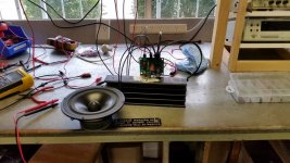

Had a few other people in the workshop so tried to keep test volumes low - 400Hz sine wave input.
.jpg")
And speaker voltage. Near enough to +26db gain
.jpg")
Unfortunately I didn't have time to put it on a scope, but I'll try for that over the weekend.
Next job: building the second board and starting on the power side of things.
And speaker voltage. Near enough to +26db gain
Unfortunately I didn't have time to put it on a scope, but I'll try for that over the weekend.
Next job: building the second board and starting on the power side of things.
Very cool. I too like the convenience of all the parts bagged individually from mouser. I've soldered together 9 of Toms boards, 3 THAT Line Drivers, 4 Mod86, and 2 Power86. Agreed that the step by step instruction is the best out there.
Tip for you. When I open the box from mouser, I turn to the page in the instructions that has all the parts listed. I match up the part number from mouser, then look at the list and write the corosponding board location on each bag, like C1, C2, R1, etc. For me, this step takes a good 30 minutes when you have parts for 4 Mod86 and a Power86, but once it's out of the way, I can put them in order, and stack all the mouser bags like index cards in a shoebox. They're all in order and you just pull the bag in front, quickly verify with Tims instructions correct part and placement on board, solder in place, on to the next.
Any who, congrats on your build. I'm glad you're having lots of success.
Very cool! Thank you for starting this build thread and sharing your build experience. It's always fun to watch my products being built and put into service.
Tom
Tom
#2 built and on the test bench. Again, pretty much 26db gain on the dot. You can see the poor cone having a fit with 50Hz haha.
.jpg")
Scope set up with input and output signals. 500mv/div on input, 10v/div on output - perfectly lie on top of each other (outputtinga bit under 50w here, if I remember how to math properly).
.jpg")
Both boards side by side.
.jpg")
Now, for the enclosure. Original plan was to put it into a 2RU enclosure, along with a pre-amp and some other bits and pieces (including a handful of modified eBay regulated PSU's that I've tested to 30V/5A output), but I'm thinking I might cast some aluminium and machine an enclosure on our CNC and go for a no-frills approach. We've recently got set up with a fairly decent foundry and have ~1000lbs of scrap aluminium, so it's a possibility! I've also got 500VA of recycled 24V transformers that I can use, along with a few toroids
Scope set up with input and output signals. 500mv/div on input, 10v/div on output - perfectly lie on top of each other (outputtinga bit under 50w here, if I remember how to math properly).
Both boards side by side.
Now, for the enclosure. Original plan was to put it into a 2RU enclosure, along with a pre-amp and some other bits and pieces (including a handful of modified eBay regulated PSU's that I've tested to 30V/5A output), but I'm thinking I might cast some aluminium and machine an enclosure on our CNC and go for a no-frills approach. We've recently got set up with a fairly decent foundry and have ~1000lbs of scrap aluminium, so it's a possibility! I've also got 500VA of recycled 24V transformers that I can use, along with a few toroids
Last edited:
Thanks for starting a his thread. I'm interested to follow it. Now that my system is mostly done, I need another project soon (I'm an addict!)
I think I'll build a LM3886DR as a gift for a family member.
I think I'll build a LM3886DR as a gift for a family member.
#2 built and on the test bench. Again, pretty much 26db gain on the dot.
Cool! Nice work!
Scope set up with input and output signals. 500mv/div on input, 10v/div on output - perfectly lie on top of each other (outputtinga bit under 50w here, if I remember how to math properly).
Math is Pout = Vout^2/(2*Rload) with Vout in volt, peak.
or: Pout = Vout^2/Rload with Vout in volt, RMS.
Tom
Cool! Nice work!
Math is Pout = Vout^2/(2*Rload) with Vout in volt, peak.
or: Pout = Vout^2/Rload with Vout in volt, RMS.
Tom
That's about what I figured; close enough to 50w!
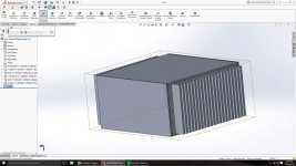
Knocked this box up in Solidworks, but the guy helping me CNC said it's not 'sexy' enough (he's a crazy German engineer haha), so we're redesigning. Still undecided if I add a preamp and some other bits and pieces in or not, I'd love matching PSU/amp boxes but running a preamp with that just complicates umbilical wiring.
Attachments
I'd shy away from umbilical cords. Using such cords increase the supply impedance which will degrade performance. There's no need to keep the amp and supply separate.
Tom
Tom
I'd shy away from umbilical cords. Using such cords increase the supply impedance which will degrade performance. There's no need to keep the amp and supply separate.
Tom
The little prototype of yours we played with last week was a tidy compact build with no detectable noise, and I think you've sold me on the Speakon connectors, and use of balanced inputs when available. I was already a convert to SMPS for lower rail voltage circuits.
Last edited:
Clearly you haven't yet had an SMPS.. Fail.. taking out your amp.
Not to worry, there's good prognosis for enjoying that singular pleasure.
Not to worry, there's good prognosis for enjoying that singular pleasure.
Chris and I spent a bit last Thursday listening to my LM3886DR + SMPS-86 amp. No blown speakers here. The combo also performed well during my testing.
I've tested the SMPS-86 with my Modulus-86 as well. Same stellar performance. About a year ago, I tested my Modulus-86 on a SMPS300RE from Connex. Worked great!
While it sounds like you had a rather bad experience, I think your experience is an isolated case and should not be generalized to switch mode power supplies in general.
Tom
I have not yet built any power amplifier with an SMPS as the PSU.
I do have a lot of user experience of mains transformers and mains to DC SMPS.
I have NEVER had a mains transformer failure.
I have had dozens of mains SMPS failures.
I do have a lot of user experience of mains transformers and mains to DC SMPS.
I have NEVER had a mains transformer failure.
I have had dozens of mains SMPS failures.
I've had mains transformers fail. I haven't personally experienced an SMPS failure. See. This is the problem with basing design decisions on personal anecdotes. You don't get the full data set.
Considering the number of switching power supplies in service world wide, you will see some failures even if the failure rate is in the ppm. I think blanket statements like SMPS = BAD are based on emotions rather than facts.
The SMPS modules I use in my SMPS-86 are well designed and very rugged. They include protection against various fault conditions, including over-current and over-voltage. On top of that, I added surge protection and inrush current limiting.
Tom
Hi tomchr,
While waiting for your PCB to come I am collecting the parts. I am curious of the function of 20k resistor + 47pF in parallel to another 20k resistor in feedback loop. Can you explain what is it for? Is it necessary? What is the downside of not having this RC network, leaving just this 20k resistor like in other designs.
While waiting for your PCB to come I am collecting the parts. I am curious of the function of 20k resistor + 47pF in parallel to another 20k resistor in feedback loop. Can you explain what is it for? Is it necessary? What is the downside of not having this RC network, leaving just this 20k resistor like in other designs.
As described on page 8 in the LM3886 data sheet:
The cap across the inputs (Cc in the data sheet) prevent quasi-oscillation as the output voltage swings near the supply rails. This results in a cleaner output and slightly higher max output power. The drawback is that Cc causes some overshoot on the transient response.
Rf2 and Cf are introduced to combat this overshoot and keep the amplifier stable.
The three parts are necessary if you want good performance.
Tom
- Home
- Amplifiers
- Chip Amps
- Neurochrome LM3886DR Build