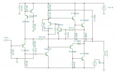
I have a Nelson Jones amp that after fourty years is in need of some work. It's a homebuilt affair by my late father, on veroboard. I've tried many other amps but always come back to this cos it sounds great. Maybe i'm used to it's sound or maybe i'm sentimental! Lately hum has become an issue, with power supply caps visibly dying. As part of it's refurbishment i'm putting in a symetrical supply to get rid of the output cap. While it's on the bench has anyone any other ideas for improvements? Getting rid of the bootstrap cap? I’ve enclosed the original circuit and my proposed rework.
Attachments

Whilst eliminating the output cap is probably a good idea in principle at least, many including myself would say that for an old and simple design with no pretensions to hifi, fitting a current source in lieu of a bootstrapped capacitor would be a backward step. If you like the great sound, keep it.
It you modify it, it will no longer be what you claim you always come back to because it sounds great.
And it will almost certainly become worse. Modifying a design is rarely a good idea. Starting over is better.
And it will almost certainly become worse. Modifying a design is rarely a good idea. Starting over is better.
Brilliant ! Pics please, lots of them 🙂
There's so little on the net about Laurence Nelson-Jones.
JLH beat him to it, by six months or so; the rest, as they say, is history.
I remember bread-boarding this, more years ago than I can remember.
Yes, its a piece of history, just the same as any Quad or Leak, leave it as it is.
There's so little on the net about Laurence Nelson-Jones.
JLH beat him to it, by six months or so; the rest, as they say, is history.
I remember bread-boarding this, more years ago than I can remember.
Yes, its a piece of history, just the same as any Quad or Leak, leave it as it is.
I would love to post pics, but it is in bits at present, awaiting rebuild. Ugly mess would be the best description! The transformer was the cornerstone to bolt various aluminum panels. Health and safety nightmare.
I think it was based on the JLH, but an exercise in lowering that designs distortion. I know my father built JLH's as well. I think the absence of discussion is because if one follows the original article then you have a good working amp.
The only problem with it is the drying out electrolytics, hence my desire to be rid of them if possible.
The position of the suggested current source looks a bit strange. I think it is intended as a substitute for R1 + R2 and associated capacitors. The input section is very similar to the one i JLH. You can find several suggestions for improving it to reduce noise on the Internet.
The Nelson-Jones amplifier is very traditional: input + VAS + output while the JLH is not. If one of them have a distinctive sound I believe it would be the JLH.
The bias control in the Nelson-Jones can be improved. As is, it only senses the output current from one half of the output pair.
If You like the sound of it I don't think You should try and improve the design. Replace the ageing parts and be happy with what You have.
I'll follow your progress with great interest; btw the original article is here:-
http://www.americanradiohistory.com/Archive-Wireless-World/70s/Wireless-World-1970-03.pdf
http://www.americanradiohistory.com/Archive-Wireless-World/70s/Wireless-World-1970-03.pdf
As drawn you'll have about 0.7VDC across the speaker. You'd need some way to keep it at 0V, a differential input stage or a servo. I'd stay with the big output capacitor, myself.
Brilliant, thanks for that site link and a possible foil to UK magazine copyright laws that can lock old articles up for 70+years even if they only exist in rotting private collections.....url]http://www.americanradiohistory.com/Archive-Wireless-World/70s/Wireless-World-1970-03.pdf[/url]
I'm not against copyright, but there is a point where the non-durability of publications means no one benefits or profits if copyright owners can't meet any demand for old articles anyway. When no profit is sought, "fair use" is a way to go for posterity, show of respect and a view of articles otherwise long lost to the public eye. The public often included friends and photocopiers "for personal use" too, back in the day 😉
Great amp.
I would not use a symmetrical supply. I would use the output cap.
Re-solder, new-solder all joints. Minimal solder, minimal diameter.
If the case is used for ground, remove all connections and set a pure ground (casing for ground sounds very very ugly).
Lots of other messes surely are, but I had to look into the amp to detect,-)
As drawn you'll have about 0.7VDC across the speaker. You'd need some way to keep it at 0V, a differential input stage or a servo. I'd stay with the big output capacitor, myself.
You missed the 4k7 in the supply line - so it would be significantly less than 0.7V. However, OP, I'd stay with the output capacitor because the output offset voltage is still probably a bit high for comfort. And the capacitor will protect your speakers in the event of a meltdown.
I remember the original Wireless World article, and I think he mentioned that, while he liked the simplicity of the JLH design, it was against his principles to end up with a design in which the standing current was so dependent on individual transistor characteristics.
Someone mentioned that the designs had "no pretensions to hifi". I'm surprised at that comment, because, despite its simplicity, it measures very well, and, by all accounts, sounds good too. And it's simple because it's Class A.
R2 in the CCS will be a pot, so i don't think offset will be a problem. Tried sticking a CCS in place of the bootstrap, and as was pointed out it made things worse, in terms of simulated distortion. I'm going to investigate the JLH input stage noise, then get it rebuilt.
For many years, Hifi has meant a lot more than just low THD. Speaker sensitivity and impedance have been falling since solid state became the mainstay of audio and for many, 5W won't be enough for the nominal 80dB dynamic range expected, excepting perhaps headphones and drivers like the specialised, high sensitivity Fostex range....the designs had "no pretensions to hifi". I'm surprised at that comment, because, despite its simplicity, it measures very well, and, by all accounts, sounds good too. And it's simple because it's Class A.
Power in the 100W+ region makes Hifi buyers pay a little more attention but unfortunately, even JLH's 10W-15W is unconvincing, regardless of how wonderful it still sounds at modest levels even now. None of this is a criticism, just an awareness of some serious expectations faced in the field. That field varies across the globe too - just saying...😉
My mind:
The most misunderstand "hifi" and "wide and linear" "frequence-response". And "live-level"-) And some TxD. Result is, my mind, not-clearness, not-clarity:
"NOT-hifi"-)))
My mind,-)
The most misunderstand "hifi" and "wide and linear" "frequence-response". And "live-level"-) And some TxD. Result is, my mind, not-clearness, not-clarity:
"NOT-hifi"-)))
My mind,-)
With some tweak and massage can become a classB (potentially) way better than the similar Philips of that era..
Attachments
- Status
- Not open for further replies.
- Home
- Amplifiers
- Solid State
- Nelson Jones 10W