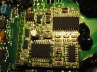
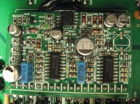
I'm working on my Memphis MCD4KW...
I have all the outputs removed. When I power up the amp and have a 4 ohm speaker attached no signal to amp there is a light hummm noise coming from the speaker.
I have 118.4VDC solid on the + rail (drain on the 360's) and no voltage on either of the other pads...
I have between -114.9VDC and -114.4VDC on both the gate and source pads that fluctuates roughly .5v up and down .1v at a time.
Now is it just me... or is something wrong here? I should have something around 5v on one pad too right? The power supply voltage was 3.??v. I finally got the output transistors, but there seems like there is going to be more to this.... don't wanna put them in and have them pop.
Amp powers up fine, no excessive draw, even with remote power. No protection light.
With no outputs installed, drive a strong 100Hz signal into the amp. Measure the DC voltage for both the high and low side FETs with the black probe on the 3rd leg and the red probe on the first leg.
Do you read ~5v on both the high and low side?
If you read it only on the low-side FETs, it could be because there is no supply for the high-side until the outputs start to produce output. In some amps, you can use a 9v battery to supply the high-side driver circuit with voltage but I've never tried it in one of these amps.
K, I'll get onto this soon. I don't have a signal generator yet so I have to use a deck. I did manage to finally buy a scope though should you need to see something else later. 😀
Should I clamp the power supply transistors? or am I good cause of no outputs?
Oh... and thanks Perry.
Should I clamp the power supply transistors? or am I good cause of no outputs?
Oh... and thanks Perry.
I suggest clamping the PS FETs but if you're careful and monitor their temperature, they should be OK.
I applied power, ground and remote to the amp. I fed the amp a 100hz sine wave via my deck, RCA voltage was 2.6VAC. I placed the black probe on the 3rd pad (source) of several output transistor locations and the red probe on the 1st pad (gate) and I have no DC voltage on either the positive or negative rails.
I'm not sure Perry. There are 3 chips and I have no idea what each one are doing, or what voltages I should be seeing. I'll get you readings first thing after work. 🙂 I got all the reading from the 494's in the power supply last night
Last edited:
494C #1: With black prob on the ground terminal
Pin 1: 2.189
Pin 2: 2.184
Pin 3: 3.305
Pin 4: 0.103
Pin 5: 1.5
Pin 6: 3.647
Pin 7: 0.023
Pin 8: 12.15
Pin 9:1.6 to 1.7 fluctuating
Pin 10: 0.624 to 0.626 fluctuating
Pin 11: 12.15
Pin 12: 10.23
Pin 13: 4.95
Pin 14: 4.95
Pin 15: 4.95
Pin 16: 0.023
Pin 1: 2.189
Pin 2: 2.184
Pin 3: 3.305
Pin 4: 0.103
Pin 5: 1.5
Pin 6: 3.647
Pin 7: 0.023
Pin 8: 12.15
Pin 9:1.6 to 1.7 fluctuating
Pin 10: 0.624 to 0.626 fluctuating
Pin 11: 12.15
Pin 12: 10.23
Pin 13: 4.95
Pin 14: 4.95
Pin 15: 4.95
Pin 16: 0.023
494C #2: With black prob on the ground terminal
Pin 1: 0.025
Pin 2: 4.96
Pin 3: 1.9
Pin 4: .039
Pin 5: 1.51
Pin 6: 3.55
Pin 7: 0.025
Pin 8: 12.15
Pin 9: 3.0? fluctuating
Pin 10: 3.01 to 3.04 fluctuating
Pin 11: 12.15
Pin 12: 10.23
Pin 13: 4.96
Pin 14: 4.96
Pin 15: 2.482
Pin 16: 2.487
Pin 1: 0.025
Pin 2: 4.96
Pin 3: 1.9
Pin 4: .039
Pin 5: 1.51
Pin 6: 3.55
Pin 7: 0.025
Pin 8: 12.15
Pin 9: 3.0? fluctuating
Pin 10: 3.01 to 3.04 fluctuating
Pin 11: 12.15
Pin 12: 10.23
Pin 13: 4.96
Pin 14: 4.96
Pin 15: 2.482
Pin 16: 2.487
I need the voltages from the 14 pin header on the audio driver board, not from the power supply driver ICs.
🙁 All 14 pins have between -106.6VDC and -115VDC when I put the black probe on the secondary winding ground and the red prob on the pins.
In looking at the readings I should have, I figured I must have been doing something wrong...
After some more studying your tutorial, I decided to try using the negative rail source pad closest to the audio section as the reference to ground. Now I have the following voltages.
Pin 1: 8.600vdc *
Pin 2: 8.700vdc *
Pin 3: 3.400vdc *
Pin 4: 8.800vdc *
Pin 5: 5.400vdc *
Pin 6: 3.200vdc *
Pin 7: 0.001vdc
Pin 8: 8.900vdc *
Pin 9: 12.50vdc *
Pin 10: 1.620 to 3.100vdc *
Pin 11: 0.003vdc
Pin 12: 2.100vdc *
Pin 13: 2.100vdc *
Pin 14: 13.98 vdc
All pins with a "*" fluctuate rapidly several point volts to nearly 1v... what could be causing this?
If I'm reading that schematic you sent me right, I should have 12v +&-, 15v +&- on 4 of them pins? Where are those voltages regulated from?
Last edited:
I also took the readings from what I believe to be the dual op amp.
Pin 1: 0.051 *
Pin 2: 115.9
Pin 3: 116.1
Pin 4: 0.044 *
Pin 5: 0.001 *
Pin 6: 7.1 - 9.2 *
Pin 7: 0.095 *
Pin 8: 14.00
Again all readings are with the neg probe on the source pad of the neg rail closest to the audio section. Voltages with "*" are fluctuating slightly except for pin 6 that one fluctuates greatly.
Last edited:
It doesn't appear that the main power supply is producing rail voltage. Do you have positive and negative rail voltage?
yes. I have -116.3 on the source and -115.5v on the gate. Placing the - probe on the center tap and + on the pads. I double checked the voltages on pin 8 too... it was the same. I put the neg probe on the source pad of the first neg rail pad.
Last edited:
If you mean that it's the same as you posted (8.9v), you need to determine why pin 8 doesn't have negative rail voltage.
Confirm that one of the secondary center taps of the small transformer are directly connected to the negative rail.
Do the various audio op-amps have positive and negative regulated voltage on their power supply pins?
Confirm that one of the secondary center taps of the small transformer are directly connected to the negative rail.
Do the various audio op-amps have positive and negative regulated voltage on their power supply pins?
- Status
- Not open for further replies.
- Home
- General Interest
- Car Audio
- Neg rail voltage on two pads?

