A few months I've stumbled across a very interesting amp...a hybrid power...but the only problem is I can't find the schematic for it...the page is found here http://members.tripod.com/~sakevich/sk1200/sk1200.html
Hope someone has an idea where I can find the schematic😕
Hope someone has an idea where I can find the schematic😕
Looks an awful lot like something we discussed here. 😀 No... the tube isn't in the NFB loop is it?
Tim
Tim
Pardon my ignorance, but I don't see how that circuit can work. Obviously, my inability to read Cyrillic is part of the problem.
How is the triode's anode made positive with respect to its cathode? All I see are connections to the insulated gates of the MOSFETs. Power MOSFETs are enhancement mode devices. Where does the necessary forward bias come from?
BTW, I use a popup stopper. Is that problematic in this situation?
How is the triode's anode made positive with respect to its cathode? All I see are connections to the insulated gates of the MOSFETs. Power MOSFETs are enhancement mode devices. Where does the necessary forward bias come from?
BTW, I use a popup stopper. Is that problematic in this situation?
Hi,
I'm not sure but I think they run the anode negative with respect to the cathode.
That's what I think it was. Popups were covering three quarters of that page in a confusing way.
Cheers,😉
How is the triode's anode made positive with respect to its cathode?
I'm not sure but I think they run the anode negative with respect to the cathode.
BTW, I use a popup stopper. Is that problematic in this situation?
That's what I think it was. Popups were covering three quarters of that page in a confusing way.
Cheers,😉
No problem here (Google Toolbar). It just shifts it aside like FRAMES, except it's an IE window pane, something java-activated.
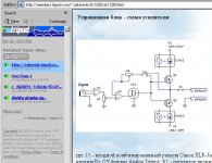
Here's what it looks like from my monitor (minus the JPEG compression 😉 ).
As for the circuit, there's still no DC path, inverted triode or not. Certainly no way to properly bias the MOSFETs, and if they are complementary it'll be deep in class C. I say it's a represenative schematic.
Tim
Here's what it looks like from my monitor (minus the JPEG compression 😉 ).
As for the circuit, there's still no DC path, inverted triode or not. Certainly no way to properly bias the MOSFETs, and if they are complementary it'll be deep in class C. I say it's a represenative schematic.
Tim
Attachments
Hi,
Looks like it...although they seem to have done either measurements on it or maybe just a sim.
Input looks as if it's a headphone jack, text says XLR (hey, I can figure out Russkie speakskie 😀 ) though.
This one's for kicks:
I ran the words right after V1a through Systran and it came up with this for a translation:
"the lamp of the rocking"...What are these guys upto?
Could that be an oscillator?
Strangest thingie...
Cheers, 😉
I say it's a represenative schematic.
Looks like it...although they seem to have done either measurements on it or maybe just a sim.
Input looks as if it's a headphone jack, text says XLR (hey, I can figure out Russkie speakskie 😀 ) though.
This one's for kicks:
I ran the words right after V1a through Systran and it came up with this for a translation:
"the lamp of the rocking"...What are these guys upto?
Could that be an oscillator?
Strangest thingie...
Cheers, 😉
The amplifier works in 2 ways...Pure Class A with very low Kr and low output power...and Class AB as a high power amplifier.
That can be achieved probably with an optron connected to the drain of the Power MOSfet which controls Qcurrent. The great thing about the amp is that there is a switch that commutates the to modes class A or class AB. The exotic connection of the tube with the grounded grid achieves optimal co-ordination between the OP amp and the Power MOSfet's with all the positives and negatives of the tube
 .
.
As you said the schematic on the site is just a representive. I'm searching for the full schematic...

That can be achieved probably with an optron connected to the drain of the Power MOSfet which controls Qcurrent. The great thing about the amp is that there is a switch that commutates the to modes class A or class AB. The exotic connection of the tube with the grounded grid achieves optimal co-ordination between the OP amp and the Power MOSfet's with all the positives and negatives of the tube
.As you said the schematic on the site is just a representive. I'm searching for the full schematic...
- Status
- Not open for further replies.
- Home
- Amplifiers
- Tubes / Valves
- Needed schematic....