Hi,
I have ordered "SC9235 2CH ELECTRONIC VOLUME CONTROLLER WITH LOUDNESS CONTROL".
I'm a bit confused as I think the datasheet has some printing error or ommision of component values.
e.g.
Supply Voltage VDD 0.3~15 (It maybe 3V to 15V). No problem as I will be using 9V supply
Value of R in series with C2 between pin 4, 5 for loudness control ?
Value of capacitor at pin 9?
INH to be connected to GND or VDD ?
I dont require backup , thus I will ommit the circuit between pin 1, 16
Component values that Im planning to use by reading the datasheet
VDD = 9V
OSC pin 8 : Rx =10K , Cx = 0.1 uF
Supply Bypass capacitor value at pin 16 =47uF
So I need your help to redraw the circuit with proper component values as there's hardly any information about this IC on internet
Thanks
Attachments
VDD is specified as -0.3 V to 15 V in the absolute maximum ratings section. That is, the IC can survive this supply voltage for at least an hour, but it does not necessarily work. If you want it to work, you have to stay in the operating supply voltage range, which is 4.5 V to 12 V, typically 9 V.
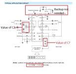
On page 7, the recommended value of the upper resistor of the loudness compensation network is specified as 8.2 kohm (see the footnote) and the lower resistor as 3.9 kohm. The upper capacitor is 1500 pF. The lower capacitor must probably be 0.1 uF, but they made a typo in the footnote and called it C1 instead of C2. You can experiment with these values until you find a combination you like.
One side of the application circuit shows a volume control with loudness, the other side without loudness - this has no branch R-C1 and the 3.9 kohm goes straight to ground. If you want to be able to switch the loudness compensation on and off, you need to add a switch with sections that disconnect the branches R-C1 and that short the capacitors C2.
The equation fosc ~= Cx•Rx on page 4 makes no sense. It should probably be fosc ~= 1/(Cx•Rx). The RC product should then be about 50 ms. As Rx has to be in the range from 12 kohm to 220 kohm, you could for example choose Rx = 100 kohm, Cx = 470 nF.
Per page 3, the not-INH pin has to be high when you don't use the backup, so tie it to the supply.
Per page 2, the not-INT pin has an internal pull-up resistor of 47 kohm typical and the switching levels of the digital inputs are somewhere between 0.3 and 0.7 times the supply voltage. When you connect a 2.2 uF capacitor to it, it will be low for roughly 70 ms after power-on, which is probably long enough for the supply to settle and short enough not to bother you.
Last edited:

WOW!
YOU CAUGHT SO MANY ERRORS!
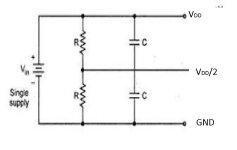
Just one more doubt - For generating VDD /2 supply , Can I replace the zener + Capacitor + Resistor with just simple voltage divider, like in attch. 2 resistor (say 4.7K) with parallel capacitors (100uF)
Thanks for the detailed reply
YOU CAUGHT SO MANY ERRORS!
Just one more doubt - For generating VDD /2 supply , Can I replace the zener + Capacitor + Resistor with just simple voltage divider, like in attch. 2 resistor (say 4.7K) with parallel capacitors (100uF)
Thanks for the detailed reply
Attachments
One side of the application circuit shows a volume control with loudness, the other side without loudness - this has no branch R-C1 and the 3.9 kohm goes straight to ground.
Correction: I meant straight to the GND-2 pin, which is at half the supply voltage in the schematic.
You can use a voltage divider with decoupling to ground, I don't see the point of the capacitor to the supply.
The capacitor has to be pretty large if you want the frequency response to be flat from 20 Hz onwards when used as a volume control without loudness: around 4700 uF to keep it within 3 dB from flat when the volume is set to -78 dB. If you want the circuit to settle in a few seconds, you then need resistors of 470 ohm or less. If you only intend to use it with loudness control, you can probably get away with a smaller capacitor, 470 uF or so.
An alternative is a split supply of, for example, +5 V and -5 V. Pins 5 and 12 then go to ground, and everything that is grounded in the datasheet application schematic then goes to -5 V. You can then also get rid of the output coupling capacitors.