Hi prorms,
I am going to repeat Tom's last request.
Please, let us know what you are doing! We can not help you if you keep us in the dark.
So, where are you getting the signal from? Please indicate the level and impedance if you know it. If not, a brand name, model and what it is.
What are you trying to send the signal into??? Again, the signal level required and the impedance level. If you don't know these things then find out and let us know.
In what system are you working? A band setup, home audio, car audio or sound reenforcement? What and where? What are the temperature limits? Is it portable, like an MP3 player? Help us out here!
Any other special features that are needed. I've built a number of buffers and amplifiers for signal processing over the years.
-Chris
Hi prorms:
If you read spanish, take a look to
http://www.pcpaudio.com/pcpfiles/preamplificadores/previoinversor/previo inversor.html
best regards
Ivan
If you read spanish, take a look to
http://www.pcpaudio.com/pcpfiles/preamplificadores/previoinversor/previo inversor.html
best regards
Ivan
10 mV IN SHOULD END UP 2.5V out
cd player after that secection of preamp it eq stage then
500 ohm volume then out to power amp
THE DISTORTION IS DOWN ABOUT 1 %
with the resitors add to the ground
cd player after that secection of preamp it eq stage then
500 ohm volume then out to power amp
THE DISTORTION IS DOWN ABOUT 1 %
with the resitors add to the ground
Hi prorms,
Where are you getting your 1% THD figure from??
-Chris
Whoa now. Are you coming right off the D/A converter?10 mV IN SHOULD END UP 2.5V out
2.5 Vrms into a 500 ohm load, plus whatever load there is on the outside? This is a tall order, and very odd I might add.500 ohm volume then out to power amp
Where are you getting your 1% THD figure from??
-Chris
Hi prorms,
I am still completely lost here. It's as if you are giving us partial hints instead of clearing things up.
Would you please take some time and write down clearly what you are doing. Please read the thread and make sure you answer all the questions.
If you have a partial schematic where your signal is coming from, consider posting it. It would go a long way towards explaining what you are doing.
-Chris
Hi prorms,
Well, your voltages are okay because you are only outputing about 3.5 Vpk.
Have you checked to see if it's oscillating? You should be using a 'scope when working with new circuits. These can slew up to 20 V / uS. Pretty fast. Make sure you decouple them right at the supply pins to your "dirty" ground. Not signal ground.
-Chris
Hi prorms,
So briefly .....
Your signal ground is "clean" (no noise) and connected directly to the input terminal to your circuit.
Your dirty ground connects only to the power supply ground. It is where bypass capacitors connect to drain away the hash and noise. Hence the name "dirty ground".
When is a ground not a ground?
When is a supply line not a supply line?
Think on these things. It's important. A major hint would be what signals may be riding on these points. Wire has resistance and inductance, so each end of the same wire are often not at the same potential in DC terms or AC terms.
-Chris
I'm sorry. I really don't have the time to explain these concepts to you. They are basic ideas.ground singal dirty ground??????
what the difference?????
So briefly .....
Your signal ground is "clean" (no noise) and connected directly to the input terminal to your circuit.
Your dirty ground connects only to the power supply ground. It is where bypass capacitors connect to drain away the hash and noise. Hence the name "dirty ground".
When is a ground not a ground?
When is a supply line not a supply line?
Think on these things. It's important. A major hint would be what signals may be riding on these points. Wire has resistance and inductance, so each end of the same wire are often not at the same potential in DC terms or AC terms.
-Chris

Hi prorms,
No, what you have is a noisy mid-point reference.
Connect a capacitor from the junction of the two resistors to ground. This will be your star point, so the input common goes there too.
You must AC couple (a capacitor) your input and output signals. You are running the circuit off a 14 Volt supply. Otherwise there would be no point in creating the pseudo ground.
-Chris
Hi prorms,
Before we get off on a tangent here, where are your supply voltages coming from and are they regulated? Are they coming from another supply? We need to see what is there before anyone can really recommend a direction.
The main problem is that the information supplied by yourself is minimal, as if it's a secret. We do need more information or you may get the wrong suggestion and complain if it doesn't work or work well.
Do you have an oscilloscope? You need one for this.
-Chris
prorms said:give the circuit 25 mV input you should notice the distortion
I know this section is were the distortion comming form
thier is no hum
That's an infinite number of circuits, since you didn't specify the potentiometer's position.
Are you saying that there is too much distortion for EVERY setting of the potentiometer? Or is it only when the potentiometer is set somewhere above its halfway point?
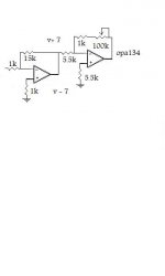
Your first opamp is an inverting amplifier with a gain of 15k/1k = -15. Your second opamp is an inverting amplifier with a gain of UP TO 101k/5.5k = -18.36. The maximum total gain = -15 * -18.36 = +275.45. For a 25 mV input voltage excursion, the output would change by a maximum of .025 v * 275.45 = 6.886 volts.
If you have +/-7v supply rails, the OPA134 can swing between -6.5v and +5.8v, according to the datasheet from ti.com. So +/- 5.8 volts is the maximum symmetric output signal level, with +/-7v power supply rails.
Did you measure the 25 mV input level? If so, what did you measure it with? If it's from specs, or from a meter, then it might be an RMS (Root-Mean-Square) value, which might mean that it is actually something more like 35 mV 0-peak, i.e. 70 mV p-p.
If your input signal really is 25 mV p-p (peak-to-peak), i.e. +/-12.5mv, then you'd probably be OK, swinging each way from zero by .0125 * 275.45 = 3.44 volts.
BUT, if you meant 25 mV 0-p (50 mv p-p), then that's your problem. In that case, you would be trying to swing the second opamp's output too close to the power rails, and would hear the results of clipping, i.e. some nasty distortion.
And if the input level was given as an RMS voltage, it would be even worse.
If one of those is the case, i.e. either 25 mV 0-p or 35 mv 0-p at the input, then you would need to lower the total gain, to avoid clipping the peaks of the signal because of the voltage-swing limitations.
You need to limit the voltage swing at the output to +/-5.8 volts, to stay within the OPA1345's specs, with a +/-7v supply.
Assuming that that was the problem, and you wanted to change the gain of the second opamp, then, for a 25 mV 0-p maximum input level, you would need a maximum total gain of 5.8/.025 = 232, or, for the second opamp, 232/15 = 15.46. Assuming you left the 5.5k resistor the same, the maximum feedback resistance could be calculated with Rmax/5.5k = 15.46, giving Rmax = 85k.
If, instead, your input level figure was RMS (about 35 mV 0-p), then, calculated similarly, Rmax should be about 60.8k.
Also, to ensure that neither opamp is oscillating at high frequency, you should probably put a 2.2pF NPO or C0G type of ceramic capacitor from the output to the negative input of opamp 1, and either that or 1 pF from output to negative input of opamp 2.
Also, you should have a 0.1 uF or larger (probably X7R-type), or 0.01 uF minimum, ceramic capacitor from each opamp power pin to ground, making sure that they are connected as close to the power pins as possible, and that the caps from the + and - pins of an IC connect to ground at about the same point (otherwise, add another 0.1 uF cap from the + PS pin to the - PS pin). You should also have a larger capacitor nearby, from each power rail to ground; probably a 10 uF electrolytic (and not a low ESR type). These values are approximate. Check the OPA134 datasheet for recommended decoupling capacitors.
You might also want to better-match the opamps' inputs' impedances, to lower the output offset voltages. I would think about using a fixed R in the second feedback loop, instead of a pot.
- Tom Gootee
http://www.fullnet.com/~tomg/index.html
Hi prorms,
Unless I can see a reasonable question with enough information to work with (or at least an attempt) I will assume you are playing and wasting our time.
-Chris
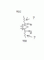
Okay. You are asking specific questions and not including enough information for an intelligent answer. This isn't the first time either.what would be a good resistor for the vcc and vss input
Unless I can see a reasonable question with enough information to work with (or at least an attempt) I will assume you are playing and wasting our time.
-Chris
- Status
- Not open for further replies.
- Home
- Amplifiers
- Solid State
- need volume booster schematic