Hello everyone. I'm very new to diy audio and making amps and such, but i've decided to give it a go and try building a 2x22W stereo amp with the TDA1554 Chip. Now i have all the parts needed but i don't have a PSU yet. Since i don't have any money to buy a new one, i was thinking of using an old AC-AC converter i have. It converts 220VAC to 12VAC 4.2 amps. The circuit however, needs DC current and not AC and it needs 5 amps to operate on full power. Would this AC-AC converter i have work ? Is the current enough ? Also, how would i convert the 12VAC 4.2 amps to DC current ?
i don't think is a good idea to use that AC-AC converter, for two reason:
1) 4.2 A are too under the requirement of your circuit
2) the AC/DC converter (the rectifier module) introduces other losses, so you would have few than 4.2 A.
I think in this forum, even if i'm new, there are alot of AC/DC rectifier schemes to work on, but if you need more info i can find some reference on it.
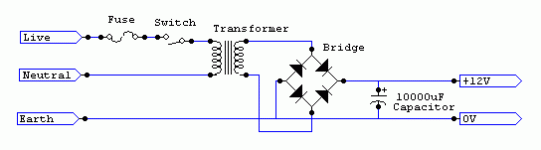
By AC-AC converter do you mean a transformer? In that case you need a rectifier bridge or 4 diodes and a big smoothing cap with 2200 µF or more. Small snubber caps across the rectifier are recommendable on top of that.
12 V AC leads to ~16-17 V DC ± regulation and mains tolerances, so you should consider to use a transformer with a lower secondary voltage. You must also take into account that there are no 220 V mains anymore and your 220 V transformer connected to a 230 V grid will give you a higher secondary voltage of 12,5 V to begin with, resulting in ~17-18 V DC, again ± regulation and mains tolerances. While such a car radio amplifier is quite rugged, overvoltage could shorten its life expectancy, if you live in a region with healthy mains voltage.
12 V AC leads to ~16-17 V DC ± regulation and mains tolerances, so you should consider to use a transformer with a lower secondary voltage. You must also take into account that there are no 220 V mains anymore and your 220 V transformer connected to a 230 V grid will give you a higher secondary voltage of 12,5 V to begin with, resulting in ~17-18 V DC, again ± regulation and mains tolerances. While such a car radio amplifier is quite rugged, overvoltage could shorten its life expectancy, if you live in a region with healthy mains voltage.
By AC-AC converter do you mean a transformer? In that case you need a rectifier bridge or 4 diodes and a big smoothing cap with 2200 µF or more. Small snubber caps across the rectifier are recommendable on top of that.
12 V AC leads to ~16-17 V DC ± regulation and mains tolerances, so you should consider to use a transformer with a lower secondary voltage. You must also take into account that there are no 220 V mains anymore and your 220 V transformer connected to a 230 V grid will give you a higher secondary voltage of 12,5 V to begin with, resulting in ~17-18 V DC, again ± regulation and mains tolerances. While such a car radio amplifier is quite rugged, overvoltage could shorten its life expectancy, if you live in a region with healthy mains voltage.
I'm in a region that doesn't really have healthy mains. Thanks so much for your help but could you tell me what diodes to get or if you can draw me a schematic ?
A little study needed first
Hi
It would be a very good idea to do a little reading about eletronics basics before you attemp to build an amplifier. you are about to play with mains voltages . im not sure if i can post a link but i will try.
Tutorials, Electronics made EASY, Williamson Labs this site is very good and is easy to understand .
I hope this will help you in your quest.
Regards Ian
The diodes should be able to pass the maximum current which is 16 A for the TDA1554. The voltage rating should be bigger than 4,5 times Ueff, i. e. more than 60 V for you transformer.
If you don't know how a rectifier is made from 4 diodes, you'd rather use a bridge rectifier. They are usually cheaper and you don't have to worry much about the connection.
If you don't know how a rectifier is made from 4 diodes, you'd rather use a bridge rectifier. They are usually cheaper and you don't have to worry much about the connection.
TDA1554 WAS MADE FOR CAR audio application voltage range is from 9 -18volts max with maximum current at 10Amps.you can use a laptop charger most have 15Volts and 5amps or you may use a 12vac transformer when rectified to give you 14volts 5amps.do not try and experiment on any other form of power supply.I believe now you have got the hang of things to to with amp circuits try and DIY a TDA2050 AMP,HERE IS THE SCHEMATIC FOR SINGLE SUPPLY,if you want in stereo mode then build 2 of the same circuit.enjoyHello everyone. I'm very new to diy audio and making amps and such, but i've decided to give it a go and try building a 2x22W stereo amp with the TDA1554 Chip. Now i have all the parts needed but i don't have a PSU yet. Since i don't have any money to buy a new one, i was thinking of using an old AC-AC converter i have. It converts 220VAC to 12VAC 4.2 amps. The circuit however, needs DC current and not AC and it needs 5 amps to operate on full power. Would this AC-AC converter i have work ? Is the current enough ? Also, how would i convert the 12VAC 4.2 amps to DC current ?
Attachments

Ok, yesterday i made a rectifier circuit from 4 diodes that i had laying around. The rectifier is properly converting the AC to DC (i tested it with an LED and a resistor). The only thing that i don't know is how many amps of current it gives off now since my shitty multimeter doesn't measure current. But thanks for the replies everyone.
The current is determined by the load, not the rectifier. Look up the datasheet for the diodes you used and it will tell you the maximum voltage and current rating of those diodes.
The current is determined by the load, not the rectifier. Look up the datasheet for the diodes you used and it will tell you the maximum voltage and current rating of those diodes.
I can't really find the datasheet since i just ripped them from an old radio i had lying around so i don't know the model number or anything 🙁
Usually the model number is printed on the diode. If it is not, the size gives an indication. 1N400x are roughly the size of a 1/4 W resistor, about 2-2,5 mm wide and 4-5 mm long and are specified for 1 A. 1N540x is bigger with about 5 mm diameter and 7-9 mm length, specified for 3 A. 16 A diodes will either be bigger or come in a case with a tap for heatsinking.
I'm just gonna try using the thing when my chip arrives and if it doesn't work i'll just buy a PSU like a normal person 😀
I need some more help you guys: My circuit need +12V DC 5-6A and a Ground (GND) connection. How can i get the ground connection ? Can anyone give me some sort of diagram for transformers ?
See post #5.
The site only refers to the wiring in countries where the mains is 120VAC and i live in a country where it's 220VAC 🙁
FOR THESE TDA1554's I USE A BATTERY CHARGER WITH 12V/10A
CAPACITY, WITH A 4AMP FAST-BLOW. YOU CAN REDLINE THIS CHIP
BY PUSHING 5AMPS BUT BE READY FOR SILENCE AND
JUST HAVE ANOTHER CHIP ON STAND-BY.
I USE AN AQUARIUM PUMP AND TOSS IN A TRAY OF ICE
BEFORE WATCHING STAR WARS FOR THE 30th TIME.
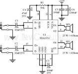
I FIND THIS A DURABLE SCHEMATIC:
44 Watt Mobile Car Stereo Amplifier | EEWeb Community
-p-
CAPACITY, WITH A 4AMP FAST-BLOW. YOU CAN REDLINE THIS CHIP
BY PUSHING 5AMPS BUT BE READY FOR SILENCE AND
JUST HAVE ANOTHER CHIP ON STAND-BY.
I USE AN AQUARIUM PUMP AND TOSS IN A TRAY OF ICE
BEFORE WATCHING STAR WARS FOR THE 30th TIME.
I FIND THIS A DURABLE SCHEMATIC:
44 Watt Mobile Car Stereo Amplifier | EEWeb Community
-p-
 Rules... no posting in capitals.
- Status
- Not open for further replies.
- Home
- Amplifiers
- Chip Amps
- Need urgent help with TDA1554 PSU !