I connected A big capaitor in series with the input of the mic preamp. and connected it to the output of the sound card it worked.I need to measure my 48V phantom power mic preamp for linearity and I don't have a clue as to how to do it. I also need to know what to use. I've searched a bit but nothing what I deemed useful showed up. The preamp input uses XLR and TRS (combo input).
I'm so new to this that I'm equal to a foetus. What kind of software do I need at the other end? And what is Big? Do I see 100 microH (troble with clarity)?
What is the best kind of testsignal to use?
Edit: I forgot to ask, what range would be considered linear?
What is the best kind of testsignal to use?
Edit: I forgot to ask, what range would be considered linear?
Last edited:
You'll need a decent soundcard and some software. ARTA, HOLMIpulse, RightMark, Audio Analyzer will all work.
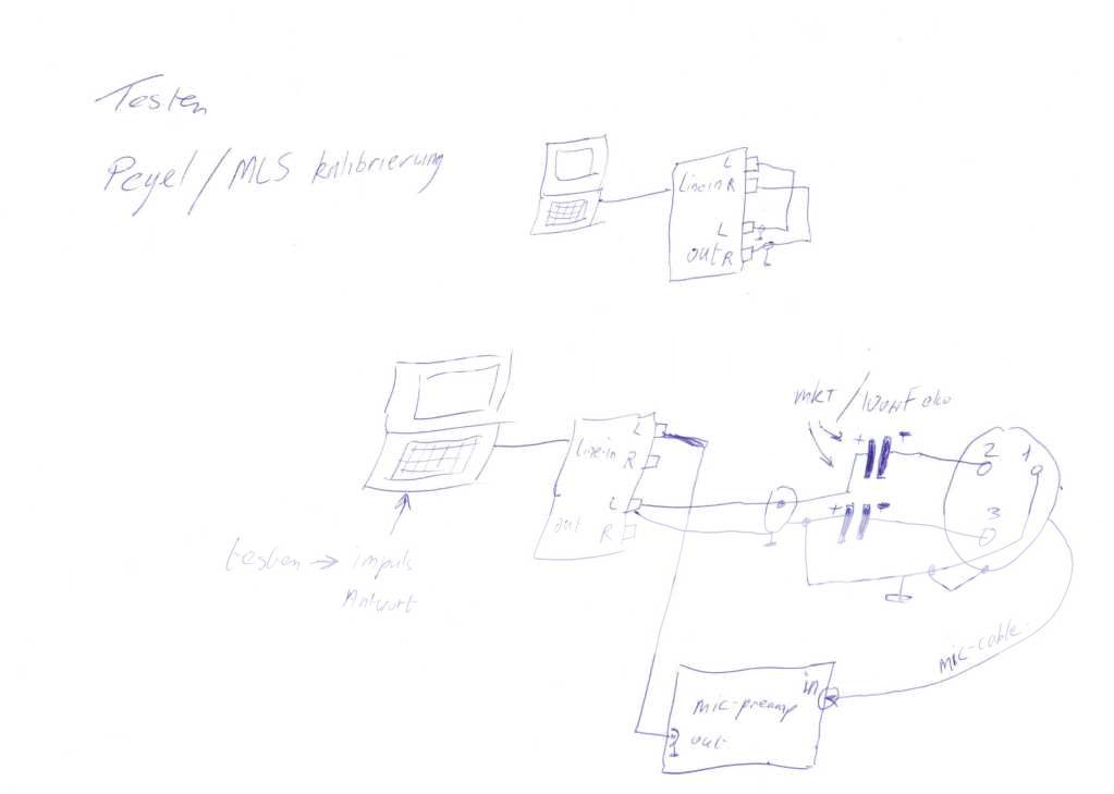
The basic setup is to feed a sine wave sweep out of the soundcard (the software does this) into the mic input. The output of your preamp is then fed back into the soundcard so that the software can draw a frequency response trace of the signal.
Helmuth's diagram above shows you how to do it. The caps are there to block the 48V phantom power. If you can turn of the phantom power, you don't need them. That is what I did on my preamp. But I also used some resistors to attenuate the soundcard output down to mic level.
Is this something you feel comfortable doing?
The polarity is wrong but doesn't matter when film capacitors are used.I'm pretty sure the polarity of the caps is drawn wrong. Phantom power provides +48V through 6.8K pull up resistors. The + end of the cap should be connected to the phantom power preamp and the - end to the attenuated sound card output.
Do I see 100 microH (troble with clarity)?
100uF
Last edited:
I need to measure my 48V phantom power mic preamp for linearity and I don't have a clue as to how to do it. I also need to know what to use. I've searched a bit but nothing what I deemed useful showed up. The preamp input uses XLR and TRS (combo input).
This is much, much simpler than people are saying. People measured this kind of stuff way before there were computers and software. Let's go back to the 1950s and ask how would we do this.
Basically you put an AC signal of some frequency into the amp. You measure it's A/C voltage. Then you measure the AC voltage at amp's output. (You need to place a dummy load on the amp's output) Then look at the ratio of the two voltages. Make a dot on some graph paper. Change the frequency and do this again.
If you don't have a sound card and software for making the tomes you can have an iPod that plays test tones from an WAV file. You can download the wav files and burn to CD if you want.
What the software does is automate this process. but if you can make some test tones and measure AC voltages and draw lines on paper you can do this. The accuracy will be limited by the accuracy of your method of measuring AC volts but if you are just looking for a graph that is good to about 1 dB you don't need professional quality test equipment.
There is some advantage of doing this my hand, yougain a better understanding of what you are doing
The polarity is wrong but doesn't matter when film capacitors are used.
The schematic does not specify film caps. If it did there would not be polarity markings.
The schematic shows polarity markings that are wrong. In a forum attended by many people that are just getting started in learning electronics we need to be as clear as possible.
100uF
Would be a damn large film cap, 100uf. Not a common part in a beginners part stash.
But I also used some resistors to attenuate the soundcard output down to mic level.
What kind of resitors, and how many, and what values and where to put them?
The schematic does not specify film caps. If it did there would not be polarity markings.
The schematic shows polarity markings that are wrong. In a forum attended by many people that are just getting started in learning electronics we need to be as clear as possible.
Would be a damn large film cap, 100uf. Not a common part in a beginners part stash.
So what kind of cap would be most useful to have, and what size for this purpose?
(For now, there is nothing in my stash)
.The schematic does not specify film caps. If it did there would not be polarity markings.
MKT is a film capasitor. and I specified 100uF to not have influence of the phase when calibrating the system.
So what kind of cap would be most useful to have, and what size for this purpose?
A normal electrolyte one is cheep.
Last edited:
What kind of resitors, and how many, and what values and where to put them?
Yes. If you must use a digital audio source as a signal generator you want to run it "full volume" an then control the volume using analog methods. The reason being is that if you use a digital volume control (with a mouse) your nice 24-bit interface starts using only 3 or 4 bits.
How to scale it down? Build an attenuater. For this purpose a simple voltage divider is fine. Use low value resistors to reduce noise, a few K-ohms is OK. What matters is the ratio of the two values
The schematic shows polarity markings that are wrong. In a forum attended by many people that are just getting started in learning electronics we need to be as clear as possible.
Hear Hear ! Hey Gary I certainly appreciate your thoughtfulness on the teachings of us Newbies.As this has been quite a steep learning curve for me personally.
") Thank You !
Thank You !
Last edited:
- Status
- This old topic is closed. If you want to reopen this topic, contact a moderator using the "Report Post" button.
- Home
- Loudspeakers
- Multi-Way
- Need to measure my mic. preamp