Hi Brian
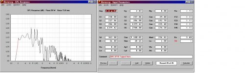
I did a quick and dirty tapped horn with your driver. It really has no gain but here it is. How close is it to what you came up with?
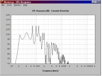
I also post a quick and dirty SP10 box. This is actually a great driver for a tapped horn. The last post is a 1 watt input for the HiVi driver. Not to shabby considering it is 84 db/watt in a normal box. THe uneven response is never there in real life so don't sweat it. This driver can really be a contender for a true tapped horn. Some more tweaking of the design could smooth it out some more and shrink it a bit. But it is really not all that bad to begin with. I'm kind of proud after about 10 minutes with the design. But me thinks shipping would kill me for this driver. 13kg! Almost 30 lbs!
Mark
I did a quick and dirty tapped horn with your driver. It really has no gain but here it is. How close is it to what you came up with?
I also post a quick and dirty SP10 box. This is actually a great driver for a tapped horn. The last post is a 1 watt input for the HiVi driver. Not to shabby considering it is 84 db/watt in a normal box. THe uneven response is never there in real life so don't sweat it. This driver can really be a contender for a true tapped horn. Some more tweaking of the design could smooth it out some more and shrink it a bit. But it is really not all that bad to begin with. I'm kind of proud after about 10 minutes with the design. But me thinks shipping would kill me for this driver. 13kg! Almost 30 lbs!
Mark
Attachments
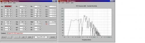
I also post a quick and dirty SP10 box. This is actually a great driver for a tapped horn.
It's not bad at all... my best modeling for it has it at an 18Hz or so corner with a small throat (60cc) and small mouth (500cc), 5:1 compression ratio. Response looks really smooth that way. Actually it's modeling better for me now than it was this morning... I guess lack of sleep is a bad thing 😉
I still prefer the SDX10 for my next project though, just because I can get 'em cheaper and easier.
Hi Brian
I did a quick and dirty tapped horn with your driver. It really has no gain but here it is. How close is it to what you came up with?
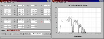
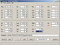
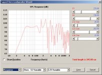
I've attached the final sim that I used for my design. Note: I used the measured parameters (done via WT3), rather than the published ones. Lots of compromises, but I wanted to get a small simple (well, as simple as a TH could be) box that could do 40 Hz up for cheap. Try the sim, then check what happens to the passband when you add about 2mH of inductance 🙂
BTW - using the published specs of the Fi X12, it will give at least 5dB more SPL from 40 Hz to 100 Hz, and not be displacement limited in the passband, in a TH that's only 0.5 cu.ft. larger.
Attachments
BTW, if there's anything in my sig of interest to you, I invite all to pack favorite CDs and visit me at Bathurst/St Clair, even on short notice. Start with a PM.
Sadly, my present music room is just 10x16 feet (small room in our 14 room home, don't ask). But OK for my one sweet spot Laz-Y-Boy chair.
But there's one thing I can say that may not be widely true on this forum of creative types: it is in fine present working order and almost always is.[/QUOTE)
That's so funny you say that, I have approx. 14 sq.ft extending from the doorway into my listening room
And there is speakers stacked everywhere. I can't really listen to anything in there so I take my stuff to
the backyard to do testing, listening and whatnot.
I downloaded HR about two months ago, and haven't looked at it since. I think I will try to muddle through it and work up a box for a Peavey Low Rider 15" , though it looks like it has a low Mms. Hope this works!
I've attached the final sim that I used for my design. Note: I used the measured parameters (done via WT3), rather than the published ones. Lots of compromises, but I wanted to get a small simple (well, as simple as a TH could be) box that could do 40 Hz up for cheap.
I've uploaded more information about this TH at the following link: The Subwoofer DIY Page v1.1 - Projects : "Proof of Concept #2"
Nice layout Brian.
The specs are not that far off from published. At least not enough to make a huge difference. How does it sound in comparison to what you are used to? I find the tapped horn to be quite close to a flh in character if it is properly done. And yours definitely appears to be properly done! Those 5 mm of excursion get put to excellent use.
Just one point of minor criticism. The link to Hornresp is a bit out of date.
Mark
Nice layout Brian.
The specs are not that far off from published. At least not enough to make a huge difference. How does it sound in comparison to what you are used to? I find the tapped horn to be quite close to a flh in character if it is properly done. And yours definitely appears to be properly done! Those 5 mm of excursion get put to excellent use.
Thanks Mark. My first impressions of the results are quite positive, particularly considering that the cabinet was not properly braced when I did my first listening test (I haven't had a chance yet to take a really good listen to the fully-braced version).
See that picture of it in the back of my car? For fun, I schlepped it in there and briefly compared the TH's output to my two Infinity drivers wired for a 2 ohm total load in their sealed enclosure. The TH absolutely slaughtered them above 40 Hz, with only slight dips in the voltage feed to the amps (compared to the significant dips down to 12V that the Infinitys were capable of inducing when driven to their peak capability). The fun ended below 40 Hz though. This reinforces my opinion that for car audio use, if I want to build a TH or any sort of 1/4 wave resonating system to my liking, I need to start with a maximum Fc of 30 Hz and work from there.
In house, I hooked the unbraced TH up to the sub output from my HT amp and gave it a loooong taste of Danity Kane's "Show Stopper" on track repeat(an obviously made-for-car-audio boom track with tones just below 40 Hz - nice way to burn in a new box, LOL). The TH absorbed the full output from the amp without any gross noises, though the enclosure did start to walk across the floor at the highest levels. Bracing was definitely needed, especially with type of ply that made available here for box-building. Birch ply this isn't! I felt a bit sorry for my neighbours hearing that tune, well at least the bass in it, for about an hour or so....
The real "win" for me here though is the spreadsheet that does the horn layout. Now I can design any TH with the same layout in minutes, even seconds, using the same spreadsheet: just input parameters and it will give me box dimensions, a cross-section and dimensions for each panel. It will even give me a rough estimate in the possible error in path length that I might experience.
Just one point of minor criticism. The link to Hornresp is a bit out of date.
It's a link to David's blog rather than the actual file. I was actually going to offer David the opportunity to host HornResp on my site, but someone beat me to it 🙂.
Is this wonderfull spreadsheet going to made available to us mere mortals? Or are yea keepsing it fer yer self?
Mark
Mark
Is this wonderfull spreadsheet going to made available to us mere mortals? Or are yea keepsing it fer yer self?
LOL - I do intend to make it publicly available eventually, after I've cleaned it up a bit. Right now it works, but it ain't pretty to look at and using it might not be as easy as it could be. If you'd like to have a look at it in its present form, let me know. Perhaps if there's another set of eyes looking at it and making suggestions while it's still in "draft" form may result in a better-looking spreadsheet in the end. Another thing - the spreadsheet can be modified without much difficulty to provide specs for a fully-tapered TH. The stepped and tapered approach seems to produce a slightly longer path length in the same space however.
Count me in. I'm all for helping you out. You have made me think constructively more than once. The least I can do is return a small favour. Although I am a spreadsheet dummie. 25 years past the expiry date on my programing course. Hated it back then and still do. But I certainly respect those who can pull it off like you do.
Mark
Mark
Last edited:
Count me in.
Well, you asked for it. See attached.
Some notes:
1. Figures in bold blue are the ones you get to play with.
2. Enter the TH's basic parameters into the corresponding cells - S1 (throat, cm^2), S4 (mouth, cm^2) and path length L (cm).
3. For "p", enter the thickness of the wood or ply (cm) that you plan to use for this design.
4. Choose an initial internal depth and height for the box that you'd like to use to implement your chosen TH and enter under "d" and "h". Adjust until the value for "L-check" is close or equal to "L". Easiest way to do this is to use Excel's "Goal Seek" function to find a value for "d" or "h" that sets "L-check" to the same value as "L". I recommend keeping a square profile for the box (e.g. set "h" equal to "d").
5. Examine "L1-Check" and "dL". These indicate the possible error that your chosen geometry (ratio of height to depth) might introduce. If it's too high, then repeat step 4 with different values for "d" and "h".
6. Use Excel's goal-seek function to set the value for "balance" to zero by changing the value for "w". This result will be the required internal width for the box to achieve the target TH alignment with the folding scheme illustrated in the spreadsheet.
7. Once you've completed steps 2 - 6, the cross-section of your TH will be illustrated in the right-hand graph. If you've completed the steps right, the graph should illustrate a cross-section consisting of panels of equal thickness. If you haven't completed the steps correctly, the cross-section will not look right.
8. The dimensions for each required panel are given in the green table at the bottom of the spreadsheet. All dimensions are in cm. Note - the bracing panels are not included in this list of panels, but you should be able to figure these out on your own. The calculations don't take the effect of bracing into effect, but once the the braces are kept small, their effect on the horn's response shouldn't be significant. If you're concerned about the effect of any bracing, try starting with a slightly larger value for S1 than suggested by the HornResp sim, then design your bracing to bring the cross-sections at different points at the horn back into close alignment with the HornResp sim.
9. The panel dimensions given assume that butt-joints are used throughout.
Hmm - maybe we should start a new thread about this spreadsheet, rather than T/Jacking this one any further 🙂
Attachments
Thanks for that last suggestion there Brian 🙂 though I'm glad you guys were throwing all that info up.
Hey Brian
I get up very early to go to work. 3:45 AM
And I go to brd very early so I can get back up.
Now!
But I will talke a look tomorrrow.
Mark
I get up very early to go to work. 3:45 AM
And I go to brd very early so I can get back up.
Now!
But I will talke a look tomorrrow.
Mark
Soooooo...after that , anyone have some tapped horns I could take a listen too? i'd be willing to drive out with some fine imported/domestic beer and pizza/ steaks @ your convenience. Anyone? Bueller?
I LOVE this forum! EXCELlent program!Well, you asked for it. See attached.
Some notes:
1. Figures in bold blue are the ones you get to play with.
2. Enter the TH's basic parameters into the corresponding cells - S1 (throat, cm^2), S4 (mouth, cm^2) and path length L (cm).
3. For "p", enter the thickness of the wood or ply (cm) that you plan to use for this design.
4. Choose an initial internal depth and height for the box that you'd like to use to implement your chosen TH and enter under "d" and "h". Adjust until the value for "L-check" is close or equal to "L". Easiest way to do this is to use Excel's "Goal Seek" function to find a value for "d" or "h" that sets "L-check" to the same value as "L". I recommend keeping a square profile for the box (e.g. set "h" equal to "d").
5. Examine "L1-Check" and "dL". These indicate the possible error that your chosen geometry (ratio of height to depth) might introduce. If it's too high, then repeat step 4 with different values for "d" and "h".
6. Use Excel's goal-seek function to set the value for "balance" to zero by changing the value for "w". This result will be the required internal width for the box to achieve the target TH alignment with the folding scheme illustrated in the spreadsheet.
7. Once you've completed steps 2 - 6, the cross-section of your TH will be illustrated in the right-hand graph. If you've completed the steps right, the graph should illustrate a cross-section consisting of panels of equal thickness. If you haven't completed the steps correctly, the cross-section will not look right.
8. The dimensions for each required panel are given in the green table at the bottom of the spreadsheet. All dimensions are in cm. Note - the bracing panels are not included in this list of panels, but you should be able to figure these out on your own. The calculations don't take the effect of bracing into effect, but once the the braces are kept small, their effect on the horn's response shouldn't be significant. If you're concerned about the effect of any bracing, try starting with a slightly larger value for S1 than suggested by the HornResp sim, then design your bracing to bring the cross-sections at different points at the horn back into close alignment with the HornResp sim.
9. The panel dimensions given assume that butt-joints are used throughout.
Hmm - maybe we should start a new thread about this spreadsheet, rather than T/Jacking this one any further 🙂
I LOVE this forum! EXCELlent program!
Thanks, but it's not that great - it still needs some work.
For example, the impedance measurement for my built stepped-TH suggests that Fc is around 43 Hz rather than 40 Hz, indicating that the TH is shorter than predicted (that's a 7.5% error - a bit too much for my liking). I'll have to recheck my assumptions wrt the path length calculations.
It's better than nothing at all! It is tough trying to get to 100% dL and stay within a required HxDxW.
I'll have to recheck my assumptions wrt the path length calculations.
FWIW, SQRT(outer wall path*inner wall path) = acoustic path-length (excluding its end correction) has worked well enough for me.
GM
- Status
- Not open for further replies.
- Home
- Loudspeakers
- Subwoofers
- NEED to hear some Tapped Horns