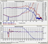
With the measurement capability that you have, did you invert the polarity of the tweeter and measure spl? That might help identify the crossover point, and possibly more.
I don't like tin solder at all, but it is lead free, which I have to admit matters. Lead is pure poison which rots your mind and IQ and motor function. We breathed it for years from leaded petrol and have 650 times more lead in our bodies than folks a 100 years ago. Lead tetraethyl was a scandal. Some of the new silver solder with flux is good too. Troels Gravesen uses lead solder still. Aka non-ROHS compliant, which stands for Restriction Of Hazardous Substances.
I have some thoughts on this peaky response. I think an HM170 Aerogel woofer is quite naturally able to run near-crossoverless. But that creates the peak:
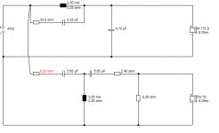
I don't see why you couldn't give it an Idunn bass crossover:
IDUNN
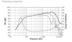
The SEAS U18RNX-P is rather similar to the Audax HM170Z18.
Tony Gee mentioned similar issues in the Auriga speaker:
Humble Homemade Hifi
One of my more complex posts. 🙂
I have some thoughts on this peaky response. I think an HM170 Aerogel woofer is quite naturally able to run near-crossoverless. But that creates the peak:
An externally hosted image should be here but it was not working when we last tested it.
I don't see why you couldn't give it an Idunn bass crossover:
IDUNN
The SEAS U18RNX-P is rather similar to the Audax HM170Z18.
Tony Gee mentioned similar issues in the Auriga speaker:
Humble Homemade Hifi
One of my more complex posts. 🙂
Attachments
Last edited:
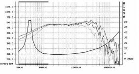
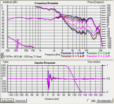
Dear Brakspear, from the curves attached in post n6 it is apparent that the peak comes from the tweeter crossover/driver. I would advise you to change the 6μ8 capacitor to 3μ9 or even 3μ3. Tweeter (and sum) output will fall (I expect about 4-5dB in the 3KHz region and progressively less up to about 9KHz), phase relationships between drivers will not change drastically, total impedance will have a (positive) peak in the 5KHz region.
On the other hand, output in the region 1.2KHz to 2.5KHz will be then somewhat lower than ideal. You would then feel tempted to change values in the woofer RC circuit to fill in the gap (by lowering the cap value – from 15μF to 10μ or even 6μ8).
So, you could begin with changing the 6μ8 capacitor in one speaker, take a measurement, proceed accordingly. Not to much work.
Regards
Thalis
Wow, thanks for all the suggestions, some of those circuits would be good to try out. For the moment I've just ordered the two 15uF caps - I got Clarity Caps ESA in the end, a bit fancier than what I was initially thinking of, but Falcon Acoustics have an offer on these giving free delivery, so they actually worked out cheaper than the rest.
Once I've got the new caps in place I'll re-measure the drivers both in combination and separately and use nearfield for the woofer below the gating frequency, then I'll know what's really going on. I may well get some cheap small value poly caps (~1uF) so I can add them in series (or parallel if that seems like the way to go) and fine tune the values. If I can't get a decently flat FR this way then that Idunn bass crossover looks interesting, Steve. I suspect the inductors I have are close in value to those shown in that schematic, so it might not need too many new bits to implement.
Can't wait for the new caps to arrive😀
Last edited:
PS. I have measured the FR with reverse polarity on the tweeters but forgot to save the graphs! They didn't look nice, phase was all over the place. I don't have an Spl meter but I may re-visit this measurement with the new caps, just to get more data on how the circuits behave.
PPS. I have a stash of lead solder, no need for the tin stuff yet!!
PPS. I have a stash of lead solder, no need for the tin stuff yet!!
Brakspear75, meet the most dangerous chemist who ever lived.
Thomas Midgley, Jr. - Wikipedia, the free encyclopedia
This man not only poisoned a generation with Tetraethyllead - Wikipedia, the free encyclopedia, but went on to destroy the ozone layer which protects us from cancer-inducing ultraviolet radiation.
I wouldn't be proud of using mind-rotting lead solder at all. But whatever floats your boat. 🙂
This man not only poisoned a generation with Tetraethyllead - Wikipedia, the free encyclopedia, but went on to destroy the ozone layer which protects us from cancer-inducing ultraviolet radiation.
If it weren't for tetraethyl lead you'd be speaking German now.
If it weren't for tetraethyl lead you'd be speaking German now.
And I always thought we won the war because of those crappy lend-lease US destroyers you sold us at exorbitant rates. 😀
Off-topic perhaps. 😱
To be fair to Thomas Midgley neither he nor anyone else knew quite how toxic tetraethyl lead would prove to be, same with CFC's - it was years before we worked out what they were doing to the ozone layer. He was in fact a very good chemist; his discoveries did what they were designed to do very well, just unlucky with the consequences.
Lead solder really isn't a problem, like most metals even when molten the vapour pressure is so low you'd probably burn your nose trying to snort lead fumes from a soldering iron. Same with the mercury everyone's so paranoid about - at room temp there's no vapour beyond 2mm of the surface. Hatters only went mad because they boiled it all day long as a bath to get leather to bend. The flux in solder is far more dangerous and quite possibly carcinogenic. So long as you don't eat the stuff using lead solder won't cause any brain damage - the Romans used to line their wine cups with lead and it took decades for them to ingest enough to cause serious issues, although some have hypothesised that it could have been a factor in the decline of the empire - who knows?
Given the amount of toxic chemicals, category 2 pathogens (mostly viruses) and radioactive tracers I've handled over the years, I don't think it'll be lead that sees me off😀
and now we're really off topic...
I find it heartening, when I throw old solder in the bin, as you do, that I'm not poisoning future generations. Or myself. 🙂
Frankly, 6" bass is a tough speaker. I never get it sounding too good. Here's one of my current ideas, with a notch around 5kHz.
The notch depends on the coil and capacitor value. I don't much like it anyway. Too bright IMO. 😕
Frankly, 6" bass is a tough speaker. I never get it sounding too good. Here's one of my current ideas, with a notch around 5kHz.
The notch depends on the coil and capacitor value. I don't much like it anyway. Too bright IMO. 😕
Attachments
Glad to hear you've ordered new caps. Going to be interesting to see if it changes anything.
I think with some simple changes to the crossover you can get a lot better results. FYI, putting caps in series reduces the value, putting them in parallel adds the values. Keep that in mind when searching for a value on the tweeter.
I think with some simple changes to the crossover you can get a lot better results. FYI, putting caps in series reduces the value, putting them in parallel adds the values. Keep that in mind when searching for a value on the tweeter.
Quick question on Holmimpulse - is there a way of doing multiple frequency sweeps and averaging the results for greater accuracy? I'm still finding my way around the software....
Still waiting for the caps
Still waiting for the caps
Hi
I cant help with Holmimpulse. I use REW which does allow multiple sweeps and averaging.
Have you tried measuring the FR's of the woofer and tweeter without the xover attached? Comparing these to the measurements you have made will give you a picture of the effects of the existing xover on the driver FR's.
Robert
The latest version of HOLM does not average sweeps. Earlier versions did. Don't know why it was dropped.
Ditto what Robert says. Always good to see what the drivers do without the crossover.
If you use the High Pass function down to the right of the impulse window, you can start the sweep higher for the tweeter. That keeps low end out of it without the crossover. Maybe high pass at 600Hz. Check this function first on the woofer to be sure you have it working.
Hello again,
I've now got the new 15uF caps in the woofer XO circuit and they sound excellent. Just to confirm the earlier data I tried shorting the resistors in the woofer circuit and measured the effect but I haven't done the nearfield measurements to extend the data to the bass range.
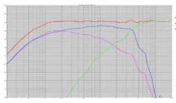
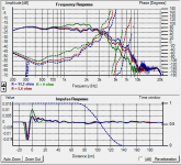
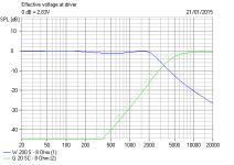
I also got a few low value PET caps so I could mess around with the tweeter XO and I've posted the graphs below. Lowering the tweeter capacitance to 3.3uF looks like the way to go. For some reason I couldn't get Holmimpulse to work with a high pass filter in place - it cut out everything below 1kHz as I wanted but at the same time stopped the sweep signal at ~2.5kHz, which was useless. If anyone knows how to get round this I'll post the data for the tweeter with and without the crossover, at the moment the graph below only shows the response with the crossover in place.
By using the caps I already have I've currently got the value at 3.1uF and am getting used to the sound - once I'm happy that this is what I want I'll get some polypropylene caps and hook it up permanently. Thanks to everyone for your assistance, I really would not have known how to sort this out by myself
I've now got the new 15uF caps in the woofer XO circuit and they sound excellent. Just to confirm the earlier data I tried shorting the resistors in the woofer circuit and measured the effect but I haven't done the nearfield measurements to extend the data to the bass range.
I also got a few low value PET caps so I could mess around with the tweeter XO and I've posted the graphs below. Lowering the tweeter capacitance to 3.3uF looks like the way to go. For some reason I couldn't get Holmimpulse to work with a high pass filter in place - it cut out everything below 1kHz as I wanted but at the same time stopped the sweep signal at ~2.5kHz, which was useless. If anyone knows how to get round this I'll post the data for the tweeter with and without the crossover, at the moment the graph below only shows the response with the crossover in place.
By using the caps I already have I've currently got the value at 3.1uF and am getting used to the sound - once I'm happy that this is what I want I'll get some polypropylene caps and hook it up permanently. Thanks to everyone for your assistance, I really would not have known how to sort this out by myself
Attachments

Good work! Looks like real progress.  Glad we could help.
Only think I now see is that you are a little hot circa 3K. At least on axis. That may smooth out of axis or at the listening position. A 3K bump can sound a little forward, but will make voices clear. Without changing the woofer inductor, it won't get much better.
As for HOLM, you may have had the low pass filter engaged as well as the high pass? That's all I can think of.
Glad we could help.Only think I now see is that you are a little hot circa 3K. At least on axis. That may smooth out of axis or at the listening position. A 3K bump can sound a little forward, but will make voices clear. Without changing the woofer inductor, it won't get much better.
As for HOLM, you may have had the low pass filter engaged as well as the high pass? That's all I can think of.
I can't believe this thread got this far without knowing what the microphone is??? Good work though, what are your plans now?
Having listened to the setup for quite a while so that I got used to the sound, it still sounded a bit too dull to me. Cymbals in particular just weren't correct, and the upper harmonics on sax were missing (I play sax so I tend to notice this sound more than others). Further tinkering with more caps led me to home in on a value of 4.7uF, and I've just ordered two Clarity Caps ESA 4.7uF so I can stop messing around with multiple PET caps in my crossover😀
Funny you should ask about the mic - it's been changed since the graphs earlier. I found an alegedly genuine (probably fake...) Panasonic WM61a capsule on fleabay for £4 so I thought why not? It's still uncalibrated and has a FR peak from 10-20kHz (confirmed with another pair of speakers - this was the only common feature) but is a lot more sensitive and is full range, so I'm happy enough with it.
Once the caps for the tweeter network are in I'll try to get a full range FR posted. That's about it for these speakers; I wanted to get these as good as I could before I start modding my Marantz CD63 KI Sig - only a few thousand more posts on that to read!! At some point I'd like to make some speakers, almost certainly from a published kit at first but that's likely to be a few years down the line.
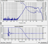
What you've done looks about right. Reduce 6.8uF to 4.7uF. That'll reduce the 3 to 6kHz range by about 2dB.
A 3.3uF takes out about 4dB, and would lose you a lot of energy above 3kHz. Might even sound like a serious hole in the response.
A 3.3uF takes out about 4dB, and would lose you a lot of energy above 3kHz. Might even sound like a serious hole in the response.
Attachments
hi guys,
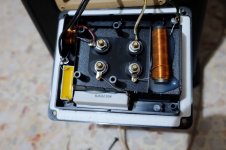
im new here and new to hifi world also. how this project has been so far?.. its been a year now.. but im interested in the result. just got myself mission 752 freedom for 21usd in mint condition 😀.. i love what i hear but im looking for xover upgrade (more to replacing caps/resistor/inductor with better one).. not really know about electronic stuff but my xover seem different compare to Brakspear75 showed.

for the woofer its just got an inductor to it, not sure what its value. and for the tweeter i can see two 5.6ohm 10w resistor and 1 4.7uf 100v, not sure about the inductor value also.
plan to replacing the caps with sonicap and both resistor with mills.. anyone got idea what the value for both inductor? might go to flat copper foil
thanks in advance guys
im new here and new to hifi world also. how this project has been so far?.. its been a year now.. but im interested in the result. just got myself mission 752 freedom for 21usd in mint condition 😀.. i love what i hear but im looking for xover upgrade (more to replacing caps/resistor/inductor with better one).. not really know about electronic stuff but my xover seem different compare to Brakspear75 showed.
for the woofer its just got an inductor to it, not sure what its value. and for the tweeter i can see two 5.6ohm 10w resistor and 1 4.7uf 100v, not sure about the inductor value also.
plan to replacing the caps with sonicap and both resistor with mills.. anyone got idea what the value for both inductor? might go to flat copper foil
thanks in advance guys
Attachments
- Status
- Not open for further replies.
- Home
- Loudspeakers
- Multi-Way
- Need to get rid of peak at crossover frequency