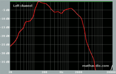
I've recently been modifying my speakers, some old Mission 752's, by adding cabinet bracing, felt etc but nothing I've found on physical mods gets rid of a frequency response peak at ~3600Hz which I think is the crossover frequency. I've searched for info on the crossover and traced the circuit in the speakers - unfortunately I don't have values for the inductors (or an LCR meter) or any detail on the drivers themselves. I think the woofer is a 6.5" Audax aerogel unit and the tweeter a Peerless 19mm but both have been re-badged as Mission drivers so I can't find the specs. The circuit diagram and FR graph are attached below - red line is the current response.
I have no experience at all with crossover design so I'm hoping someone will be kind enough to point me in the right direction; for now I have a few questions
1) The speakers are over 20 years old and have never been re-capped - could the unwanted peak be due to the 15uF non-polar electrolytics failing?
2) The 6.8uF capacitor is a polystyrene dielectric, would changing this to polypropylene give a worthwhile improvement in sound?
3) Does anyone know the values for the inductors - if not can anyone still suggest which component I might best replace and with what value to give a flatter FR?
Thanks a lot,
Mark.
Attachments
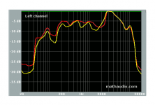
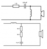
Are you sure that those resistors series with the woofer cap are 56 ohms? Because it does not make much sense..... 112 ohms in series with 15uF does virtually nothing in that circuit. If they are REALLY 56 ohmers, try to reduce their value to somewhere around 10-12 ohms, and listen again. Also there is a good chance that the 15 uF bipolars dried out, so replace them with similar value caps (foil cap will be even better than bipolar).
That's quite a peak! Must sound bright.
If that is the crossover frequency, you could try a modification by reducing the value of the tweeter cap. If it's 6.8uF now, try half or something similar. What that will do is cross the tweeter higher, maybe attenuating that peak. You spread the crossover frequencies a little.
Easy to try, and you should be able to hear and measure it. Not a final solution, but a path to one.
EDIT: Cross post again.
Here are some other things you could try:
It won't hurt anything to run just one section at a time and it will tell us a lot about what is going on.
Here are some other things you could try:
- Bypass one, then both resistors. Use a bit of wire or a clip lead.
Measure each section on its own. Post those measurements here.
Measure the woofer trying the resistor bypass
It won't hurt anything to run just one section at a time and it will tell us a lot about what is going on.
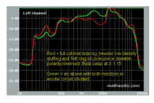
Thanks for the suggestions - below are the FR's for the individual drivers, tweeters measured at 1m and woofers nearfield at 5cm, hope that's the right way to do it!
I haven't bypassed the resistors yet - this is FR as the circuit is shown (ignoring errors...). I'll post the FR's with the resistors bypassed once I've done them.
I haven't bypassed the resistors yet - this is FR as the circuit is shown (ignoring errors...). I'll post the FR's with the resistors bypassed once I've done them.
Attachments
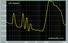

You have surely measurement errors (spikes present on both drivers).
Besides that, the right method is to gate, without gating you measure also the reflections. And are you sure your mic is flat?
Ralf
Besides that, the right method is to gate, without gating you measure also the reflections. And are you sure your mic is flat?
Ralf
Thanks for the measurements, they say a lot. 
Don't really understand that crossover, unless things have really aged over 20 years. For the moment, I'd say leave both woofer resistors in bypass and then worry about the tweeter.
Don't know why the tweeter plot falls off like that. Could be any number of things.
If it were mine, I'd want to flatten it some. A little roll-off will sound good, that that's too much. Looks to me like a peak caused by incorrect values.
Try something like a 4uF or 5uF cap. Maybe as low as 3uF. That might kill the bottom peak of the tweeter and flatten it some. If you can get a handful of ~1uF caps and stack them in parallel, that can help you narrow down the value that will work. No need to go expensive, just get what you can to test with.
Don't really understand that crossover, unless things have really aged over 20 years. For the moment, I'd say leave both woofer resistors in bypass and then worry about the tweeter.
Don't know why the tweeter plot falls off like that. Could be any number of things.
- Incorrect component values
- Bad tweeter
- Mic response
- All of the above
If it were mine, I'd want to flatten it some. A little roll-off will sound good, that that's too much. Looks to me like a peak caused by incorrect values.
Try something like a 4uF or 5uF cap. Maybe as low as 3uF. That might kill the bottom peak of the tweeter and flatten it some. If you can get a handful of ~1uF caps and stack them in parallel, that can help you narrow down the value that will work. No need to go expensive, just get what you can to test with.
Hi Ralf, I only have the one mic and it's not calibrated, but I'd hope it's not out by 5dB at 3600Hz! If it is it's a strange coincidence that it aligns with the crossover freq so exactly. Also the speakers do sound bright, although not unacceptably so (maybe I've just got used to it).
Not sure what you mean by gating but I almost certainly don't have the equipment to do it...I thought the idea with measuring woofers nearfield was to minimise reflections? I'm happy to try other measurement methods so long as they don't cost much - I can spring for a few caps but I'd rather not buy a new mic/soundcard/software etc.
Not sure what you mean by gating but I almost certainly don't have the equipment to do it...I thought the idea with measuring woofers nearfield was to minimise reflections? I'm happy to try other measurement methods so long as they don't cost much - I can spring for a few caps but I'd rather not buy a new mic/soundcard/software etc.
I doubt you need to worry about a new soundcard. The mic, hard to say without knowing what it is! 🙂
(but it's not likely off at the crossover frequency)
(but it's not likely off at the crossover frequency)
I concur that the mic is unlikely off right at the crossover frequency, but I'd take the results with a grain of salt.
Proper measures are done gated far field, and you only need a software able to do that. Fortunately some are free, like Arta which I use. There is a document about this method:
http://audio.claub.net/tutorials/FR%20measurement%20using%20ARTA.pdf
Since the gated method has inherently a low limit (in my room is around 200Hz), under that limit the only method is a near field response, then merged accordingly with the far field response. Search a very good document by J Bagby about that, but you can forget for the moment this aspect since you are interested more in what happens higher in frequency.
But in order to compare the two drivers, at least redo the measures under the same condition (1 m or something like that, I use 80 cm).
Ralf
Thanks for the info on ARTA, Ralf . I've installed it to do some proper gated measurements but at the moment it's not working with my hardware - I'll get it sorted somehow! Once I've done the gated FR I'll post the data.
. I've installed it to do some proper gated measurements but at the moment it's not working with my hardware - I'll get it sorted somehow! Once I've done the gated FR I'll post the data.The circuit below is a good stab at a typical 6" driver.
Audax HM170Z10 Aerogel 17cm 6.50" woofer
I can't say what the exact value of the tweeter resistor will be though. I'm guessing 3.9R, but select on test.
Audax HM170Z10 Aerogel 17cm 6.50" woofer
I can't say what the exact value of the tweeter resistor will be though. I'm guessing 3.9R, but select on test.
Attachments

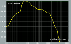
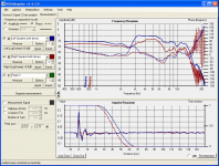
It seems ARTA really doesn't like my pc, so Holmimpulse it is, thanks ief. The measurements were taken on axis at 80cm with the closest surface being the floor at ~ 75cm so despite my mic not being sensitive enough to pick up the reflections the data should be accurate enough around the crossover frequency. Please note that I've removed the shorting links across the resistors as this cut the bass output too much without doing much to the unwanted peak - a comparison of the FR's using the old measuring method is attached.
There's quite a difference between the speakers so I guess the caps probably have dried up - I'll replace the 15uF caps first and then see what the measurements look like. Any recommendations as to sensibly priced replacements - I'm happy to go with the suggestion of foil caps as being higher quality? And a cheap source in the UK?
There's quite a difference between the speakers so I guess the caps probably have dried up - I'll replace the 15uF caps first and then see what the measurements look like. Any recommendations as to sensibly priced replacements - I'm happy to go with the suggestion of foil caps as being higher quality? And a cheap source in the UK?
Attachments
Glad to see you've got HOLM running. It's my favorite. You can loosen up the gate a little. 800Hz is high.
In the USA I get crossover caps from Parts Express of Madisound. I find the best value for money are the Janzen Cross Caps. Sound great, low cost. Solen also work fine. Bennic are OK, but I try to use other brands.
Jantzen Audio 15uF 400V Crosscap Capacitor
Solen 15uF 400V Polypropylene Capacitor
15uF 100V Electrolytic Non-Polarized Crossover Capacitor
These will cost more in the U,K, of course.
It would still be nice to see the woofer without the resistors. Try again after you get new caps. Let's see what the curves show. In your previous measurements the woofer looked better without the resistors.
Wilmslow Audio have a good range of capacitors and coils:
Capacitors
I get the standard 250V MKP polys.
I usually get 10W wirewound resistors at Maplin for the values I need:
Wirewound 10 Watt 1 Ohm Resistor | Maplin
You can pick up a 40W soldering iron there too. The new tin solder doesn't work with the old 25W irons.
Capacitors
I get the standard 250V MKP polys.
I usually get 10W wirewound resistors at Maplin for the values I need:
Wirewound 10 Watt 1 Ohm Resistor | Maplin
You can pick up a 40W soldering iron there too. The new tin solder doesn't work with the old 25W irons.
- Status
- Not open for further replies.
- Home
- Loudspeakers
- Multi-Way
- Need to get rid of peak at crossover frequency