Will someone take the attached schematic and work up a load line for me so I have something to check against when I am working thru it? The amps designer no longer has his notes and the numbers I get are not making sense to me.
Also any good articles on working up load lines for single ended cathode biased amps would be most helpful. Everything I have found so far has just confused me further.
Thanks in advance to whomever takes some time out their day to help me. I realize it is no quick and simple thing and that I am asking for a lot. Maybe I can help you out with something in trade. I have over 400 tubes. I may have something you need.
Jeff
Attachments
'....and the numbers I get are not making sense to me.' -which number you are talking about? The designer is a member here and this one is a fine design.
For loadline calculation you may like to check:
Load Line Calculations – wauwatosa tube factory
Tell us your situation/actual problem so that we can help you. You have build the amp and you are getting weird voltage reading?
Regards
For loadline calculation you may like to check:
Load Line Calculations – wauwatosa tube factory
Tell us your situation/actual problem so that we can help you. You have build the amp and you are getting weird voltage reading?
Regards
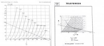
Looking at the curves, the working point is correct. It runs the tube somewhat hard, but it is entirely in specification.
-2V at 180V anode-cathode gives about 20mA of plate current judging from the triode curves. 20mA plate current yields 4W dissipation. Maximum is 4.5W for G2 and Anode dissipation combined. So the tube is used at 90% of permissible dissipation.
The schematic, is okay, i would put 100R 1W carbon comp on the socket of the D3A between G2 and Plate.
G3 can indeed be grounded, to provide -2V on G3 or alternatively you can tie it to the cathode, it matters very little in the practical world.
Cheers,
V4lve.
(180-2) volt x 20ma =3.56 watt, what am I missing.
v4lve lover your input is spot on. I used e180F, ef184, e280f, c3m as 300b driver and found that G3 connection, to anode or cathode, does not make any significant difference. But no matter what kind of pot I use I always put right size grid leak resistor.
Regards
v4lve lover your input is spot on. I used e180F, ef184, e280f, c3m as 300b driver and found that G3 connection, to anode or cathode, does not make any significant difference. But no matter what kind of pot I use I always put right size grid leak resistor.
Regards
Strange symbol used for the rectifier. It looks like the cathodes are connected to the transformer and the positive voltage is taken off the anode.
The bar on the right should be the cathode and the anodes should be connected to the transformer.
The bar on the right should be the cathode and the anodes should be connected to the transformer.
Use a good datasheet. Best to find one with working data, compiled by a junior engineer as part of his training. From the source, W.E.:
http://www.tubebooks.org/tubedata/we300a_b.pdf
It is a soft triode. The load impedance is NOT critical!! The new-plan's 5.6k is higher than anything on the sheet, true. However look at the trends. A 2:1 change, say from 1.7k to 3.4k, reduces power and distortion, but not a lot. Going further, 5.6k is probably down on Watts and on THD, a very reasonable choice. OTOH if for some reason you can only load it in 2k, that will work also.
Attachments

- Home
- Amplifiers
- Tubes / Valves
- Need some load line help