Arnulf, measurments were taken from grid to ground and anode to ground.
I will take high res pictures later and post them here.
David
I will take high res pictures later and post them here.
David
While you are at it, please measure what's going on with the cathode (or grid to cathode voltage) just in case. Grid to ground reading is a bit pointless should there be some kind of common mode noise (perhaps induced from the outside - pictures should reveal more) on supply rails.
Up until the grid of the second
triode everything seems fine. The hum seems to be added by the second tube.
Up until the grid of the second tube everything "seems" fine, but that's because the noise is low enough that you can't see it at the scope sensitivity. Amplify it by 30 or so, and you see it.
Looks like PS noise on the common.
Sheldon
You've got some conflicting posts. At first it seems all is good untill you hook up the TT. Now you're saying it hums considerably nomatter.
Either way, such gripes can be frustrating for sure. If psu is good, circuit is wired good, perhaps the 1st gainstage is too close to offending sources such as transformers or a wire with AC on it???
Biasing the heaters to a positive voltage is just as good as using DC btw.
Hope you solve it without too much hairloss😉
Well, at first the hum got much louder when I connected the turntable. It seemed all
right without the source connected. I solved this issue but now I've still got a
constant hum in the background that I can't get rid of.
The whole circuit board is now enclosed in copper clad circuit board. I don't think it
picks up the hum from the transformers.
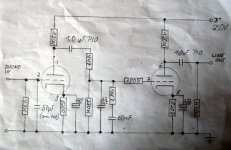
The first stage amplifies by 30, there is no measurable hum on the anode of this
stage or anywhere in te RIAA network. Then the 2nd stage amplifies by 30 again and
adds this nasty hum to the previously (seemingly) fine signal. Why is that?
Sheldon is right of course, I can't see any ripple on the B+ rail, that doesn't mean it's not there.
I'll post those pictures of the whole construction later today.
David
right without the source connected. I solved this issue but now I've still got a
constant hum in the background that I can't get rid of.
The whole circuit board is now enclosed in copper clad circuit board. I don't think it
picks up the hum from the transformers.
The first stage amplifies by 30, there is no measurable hum on the anode of this
stage or anywhere in te RIAA network. Then the 2nd stage amplifies by 30 again and
adds this nasty hum to the previously (seemingly) fine signal. Why is that?
Sheldon is right of course, I can't see any ripple on the B+ rail, that doesn't mean it's not there.
I'll post those pictures of the whole construction later today.
David
Hallo everybody,
I built quite a few tube RIAA pre amps and I learned to do that noise free, but it is also very tricky, to choose the right point for star grounding, to keep the tubes far away from the power transformer, all that is important. The RIAA pre amp is soooo sensitive, it will pick up hum out of the air. Tube shields do help a lot, too. I use standard a 12 volt controller for the filaments, this improves the quality of the DC signal very significantly and did remove the last vestiges of hum in my pre amps. I also use standard 4 stage filtering with bypass caps, tring to loose at least 30 volts over my filter chain rcrcrcrc. That is sufficient for goo filtering. Bypass caps (poly) at the begin and end of the filtert chain help to remove switching noise injected by diodes and high frequency noise. My RIAA pre amps run with 250 volts B+, that is what I aim for, and I hold about 0,6 volt ripple noise, I cannot get rid of. That is very acceptable, maybe a controller circuit will further improve that, but the pre amp is so quiet enough for headphone use, so I am happy. If I can be of further assistance, please drop me a pm.
Kind regards from Holland
Good listening
Bernd
Attachments
Last edited:
I did this block diagramm of my RIAA pre in my lunch break. It represents the wiring
and placing of components quite well.
and placing of components quite well.
An externally hosted image should be here but it was not working when we last tested it.
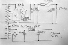
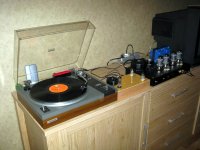
In my phonopre I have a seperate powersupply using a EZ81 rectifier, followed by a MOSFET buffered voltage regulator. The heaters are DC powered as well. When I place the preamp on top of the supply, it hums too much. As I increase the distance the hum reduces proportionally. The powersupply is connected with a too short cable, about 75cm, so I cannot experiment with how far away is optimum. But as it is I have the supply as far away as possible.
The riaa network only filters the high frequencies, so at 50Hz you have all the gain, and it is therefore very sensitive to stray low freq radiation. Copper and aluminimum doesn't do much at low freqs, you need mu-metal or iron for that.
Even the orientaion and direction of transformers can have a large effect if their distances to gain stages cannot be increased.
I know how frustrating this type of problem can be, and have experienced hum on a near copy of a circuit that does not hum, and never been able to figure out the problem before giving up and just doing some other circuit.
Last edited:
I'll take some 47uf/450V caps and some 680R resistors home tonight and add another
3-4 RC filter stages after the MOSFET regulator. Wich I'll have to change as well as the RC filters will take away about 55V. I'll try with B+ of 200-250V.
If that doesn't work I think I might throw in the towel and maybe switch to ECC83 or
similar and another circuit.
I've built several tube RIAA stages over the years, standard RCA, with pentodes, etc.
never have I had this much trouble. My first tube project was a RIAA preamp built
from junk inside a small wooden box. The transformer was no more than 2cm below the tube sockets. It looked crap but worked well. Maybe I'll dig out the schematics I
used back then...
Though I really would like to do it using some of the E88CC's I've got knocking about.
It is a nice tube but maybe has something of a diva?
Luckily I still have 3 weeks until my friends birthday, I'll cook something up eventually.
David
For the last time, post a photo which clearly shows your arrangement. You said there is no noticable ripple on supply rail so this could be just a matter of induced (common mode) hum in incorrectly placed, unshielded and/or untwisted wiring. Adding more RC stages to supply rail will not alleviate the problem.
It is impossible to guess what is wrong without all the information (and even then it may be very difficult).
It is impossible to guess what is wrong without all the information (and even then it may be very difficult).
Last edited:
+1 on Arnulf's post.
Adding RCs on a ripple free line wont do anything.
I use the E88CC on all my guitar amps, and have tons more gain than what a phonopre has, and they are dead silent.
Orientaion of transformers, and twisting wires, 'general lead dress' as it's called, is vital.
Adding RCs on a ripple free line wont do anything.
I use the E88CC on all my guitar amps, and have tons more gain than what a phonopre has, and they are dead silent.
Orientaion of transformers, and twisting wires, 'general lead dress' as it's called, is vital.
The first stage amplifies by 30, there is no measurable hum on the anode of this
stage or anywhere in te RIAA network. Then the 2nd stage amplifies by 30 again and
adds this nasty hum to the previously (seemingly) fine signal. Why is that?
My point is that the hum is there all along. You just don't see it until it is fully amplified by the final stage. Let's say you have a standard 5mV cartridge. For sake of argument, let's say you want the hum to be 80 dB down (makes the calculation easy). That's a factor of 10,000, or 0.5uV. So if you have that noise on your initial grid, you will never see that with your scope - remember you are looking at 5mV per division. Now multiply that by 30, and you have 15uV. Still not gonna see it. Multiply it again by 30 for the second stage, and now you are at 0.5mV. Now you begin to see it.
Sheldon is right of course, I can't see any ripple on the B+ rail, that doesn't mean it's not there.
I'm not saying it due to ripple on the B+ rail. It could be. More likely, it's noise on the common.
Sheldon
I did this block diagramm of my RIAA pre in my lunch break. It represents the wiring
and placing of components quite well.
An externally hosted image should be here but it was not working when we last tested it.
I see one problem there, and one potential problem.
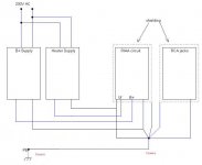
Your heater supply and B+ supplies should be separate complete loops, then connected to the main star. As drawn, both your heater and B+, return through your connection from the input common to the chassis ground. Supply ripple will generate noise on that leg.
Also, the diagram is not detailed enough to show your internal supply connections. Your commons should be returned to the final capacitor in the supply.
Sheldon
Like this. You'd have 5 wires from the power supply to the preamp, HV and common, filament and common, and earth. Earth the supply chassis, and connect this earth to the preamp chassis.
Attachments
Last edited:
I read somewhere that it is good to make the earth star point at the input phono jack sockets? Worth a try I suppose. I made a small RIAA preamp in a diecast box, three dual triodes with screening cans and all circuitry crammed into a box measuring 6" x 3" and 2" high. I used floating DC heater supply elevated to around 30V with all ground wiring going to a star at the bus-bar ground linked phono jacks. Absolutely dead quiet when it comes to hum/noise, perhaps helped by a separate power supply box.
Hum problems can be a devil to sort sometimes and after trying so many things one begins to lose heart. Keep in there, try the tips given by the other Forum members and I am certain you will get success. Les
Hum problems can be a devil to sort sometimes and after trying so many things one begins to lose heart. Keep in there, try the tips given by the other Forum members and I am certain you will get success. Les
I read somewhere that it is good to make the earth star point at the input phono jack sockets?
Yes, for sure, if the phono jacks are not isolated from the chassis. If the jacks are isolated, it's not as critical, but it can't hurt.
I used floating DC heater supply elevated to around 30V with all ground wiring going to a star at the bus-bar ground linked phono jacks.
Elevated heater supply is a good idea. Don't know if that was done here. If it is, the heater connection to the star would be replaced by a heater connection to a voltage divider on the HV supply.
Sheldon
Ok, now I've rewired the preamp according to Sheldon's redrawn diagram. It was a partial success. The amp is now quiet as long as no record player is connected.
As soon as I plug that in it starts again. Well, small steps at a time...
A closeup of the circuit board itself.
http://dplinks.ath.cx/ebay/Inside1.jpg
David
As soon as I plug that in it starts again. Well, small steps at a time...
A closeup of the circuit board itself.
http://dplinks.ath.cx/ebay/Inside1.jpg
David
Last edited:
Ok, now I've rewired the preamp according to Sheldon's redrawn diagram. It was a partial success. The amp is now quiet as long as no record player is connected.
As soon as I plug that in it starts again. Well, small steps at a time...
A closeup of the circuit board itself.
http://dplinks.ath.cx/ebay/Inside1.jpg
David
Having looked at your construction technique I would say it is quite possible that the pre-amp is oscillating when you plug in the TT. The wire lengths are long and there is a lot of capacitance between them and the shields - on the grids this will introduce an LC resonant circuit that compromises stability and may cause VHF oscillations which when rectified produce all sorts of interesting effects including loud hums and buzzes. Try a 220 - 1K resistor right at the grid of each tube section. Just lift the wire and solder the resistor in series with the lead right at the socket pin.
This may or may not help, but could prove revealing. A small amount of resistance at the plate (<100 ohms) may also help.
Good luck.
Second that Kevin. Potentially a good amount of stray capacitance there. I always put the plate resistor, cathode resistor, and grid stopper (if necessary) right on the socket. For signal wires, I prefer tightly twisted 30 gauge wire to shielded coax. Easier to work with and does a good job of rejecting noise pick up.
Also check the location of your tt ground cable. Try the chassis earth point, and also the main star.
Sheldon
Also check the location of your tt ground cable. Try the chassis earth point, and also the main star.
Sheldon
Another comment I would make is that the filament circuits should be completely separate and represent a closed loop in and of themselves. The filament circuit can then float on a bias voltage in order to prevent coupling between the cathode sleeve and filament, and the grounds are not modulated by the high currents in the filament circuit. The IR drop across a single ground wire carrying all of the supply currents can be modulated by the filament supply particularly with ac filaments.
- Status
- Not open for further replies.
- Home
- Amplifiers
- Tubes / Valves
- Need some help with RIAA Preamp