Hello all.
I am in the process of trying to design my own tube amplifier. It's actually more of a redesign of an existing amplifier schematic. Having never designed my own amp before a friend suggested it might be smart to run the design through an LTSpice model to make sure I haven't overlooked something. Good advice. Well, having never worked with LTSpice before I have run into a few issues that I can't seem to solve on my own.
Background on the amp:
Issues:
- LTSpice didn't have library files for the 6sn7, 6sl7 or the KT120/KT150/KT170 tubes. This was partially solved when a friend referred me to the following thread here.
https://www.diyaudio.com/community/threads/vacuum-tube-spice-models.243950/
I downloaded the library and inserted the files into my schematic (I think I did that right). Ayumi did not have the KT120/150/170 in the library to I inserted the KT88 as a placeholder until I find a suitable library file for the biggerl KT tubes.
I would like to reiterate that I am no expert amp designer (first one) and I am not an expert LTSpice ( first time using it) so any help offered would be appreciated very much. Here is the schematic.

I am in the process of trying to design my own tube amplifier. It's actually more of a redesign of an existing amplifier schematic. Having never designed my own amp before a friend suggested it might be smart to run the design through an LTSpice model to make sure I haven't overlooked something. Good advice. Well, having never worked with LTSpice before I have run into a few issues that I can't seem to solve on my own.
Background on the amp:
- 6sn7/6sl7 preamp and phase inverter stages
- was push/pull el34 output tube based...would like to move to push/pull KT120/KT150/KT170
- would like it biased class a1
- adding an ac bootstrapped follower to the inverter for more gain so I can drive the new output tubes
Issues:
- LTSpice didn't have library files for the 6sn7, 6sl7 or the KT120/KT150/KT170 tubes. This was partially solved when a friend referred me to the following thread here.
https://www.diyaudio.com/community/threads/vacuum-tube-spice-models.243950/
I downloaded the library and inserted the files into my schematic (I think I did that right). Ayumi did not have the KT120/150/170 in the library to I inserted the KT88 as a placeholder until I find a suitable library file for the biggerl KT tubes.
- I can't find a library file for the LM334 current source
- I can't find an output transformer file and lack the skills to create my own
- I can't model the negative feedback because it comes from the 16 ohm tap on the transformer.......which I haven't been able to figure out
- Lastly but most importantly when I run the simulation it comes back with a singular matrix error around the LM334 node, which I can't figure out
I would like to reiterate that I am no expert amp designer (first one) and I am not an expert LTSpice ( first time using it) so any help offered would be appreciated very much. Here is the schematic.
- can't find a library file for the LM334 current source You can download many goodies here
- I can't find an output transformer file and lack the skills to create my own Download "ULTPP16.txt"
- I can't model the negative feedback because it comes from the 16 ohm tap on the transformer.......which I haven't been able to figure out Pick a model from above lib. See attached for LTSpice model. The difficult part is UL tap calculation and series Sec taps inductance, they're a division of 1st tap you can see their relation.
- Lastly but most importantly when I run the simulation it comes back with a singular matrix error around the LM334 node, which I can't figure out Disable components one by one isolate offending one.
Attachments
Last edited:
Chances are that the singular matrix is gone when you replace the current source with a realistic LM334 model.
I found the simple ideal current source being very close to the reality of a depletion mosfet current source
First off, thank you for the help and straightforward explanations. I have the LM334 on the schematic as well as the output transformer. As far as the feedback goes, I will make the connection on the schematic but I will have to dig further to understand the rest of what you said. I think I know what you are referring to, and I know what it was on the original design but not sure what it should be for the new design. I replaced the current source with the LM334 and the error went away.To find other tube models, search this forum using ".subckt kt170" or other models.
- can't find a library file for the LM334 current source You can download many goodies here
- I can't find an output transformer file and lack the skills to create my own Download "ULTPP16.txt"
- I can't model the negative feedback because it comes from the 16 ohm tap on the transformer.......which I haven't been able to figure out Pick a model from above lib. See attached for LTSpice model. The difficult part is UL tap calculation and series Sec taps inductance, they're a division of 1st tap you can see their relation.
- Lastly but most importantly when I run the simulation it comes back with a singular matrix error around the LM334 node, which I can't figure out Disable components one by one isolate offending one.
I will search further for the other spice models as time allows. Thank you again.
Chances are that the singular matrix is gone when you replace the current source with a realistic LM334 model.
You are absolutely correct!
I am just say where you or most people found difficulty in understanding transformer model. Look at the spread sheet model can get you somewhere I hope, the model you see is generated by the spread sheet, just like Paint Tools generated tube model, the spread sheet generate transformer model. You need to insert the correct parameters for your transformer.
https://www.diyaudio.com/community/threads/spice-transformer-model-spreadsheet.181578/
https://www.diyaudio.com/community/threads/spice-transformer-model-spreadsheet.181578/

I'm a bit surprised by the use of 6SL7 for the LTP/CF and 6SN7 for the input stage. Usually is the other way around.
I'm going to model it both ways. Just happened to be the one I started with.I'm a bit surprised by the use of 6SL7 for the LTP/CF and 6SN7 for the input stage. Usually is the other way around.
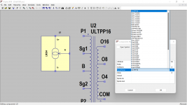
Ok, apparently I am still not doing something right. I had a working simulation before I added the transformer model.
I have added the transformer symbol to the schematic...simple enough
I have used the transformer worksheet to create the .subckt file
I have used a Spice directive to add the subckt file to the schematic (just like I did for the KT88 tubes and they worked)
Here is a picture of the schematic with spice directive and a picture of the error message
I am not sure what I am doing wrong?
Thanks in advance for the help.
I found the drop down menu and once I choose a470 it recognized the circuit. I am still getting good output voltage on the left side of the phase splitter but not the right. I think I just have to find out why it is not balancing correctly. Thanks for the brain jog from the question above.Is the subcircuit called ultpp16 or a470?
Two other comments:
1. You often have wire ends sticking out below the component symbols. If they go all the way to the other side of a capacitor, you have a short that is barely visible on the schematic.
2. For the feedback to work, you presumably have to ground the COM pin of the secondary of the transformer.
1. You often have wire ends sticking out below the component symbols. If they go all the way to the other side of a capacitor, you have a short that is barely visible on the schematic.
2. For the feedback to work, you presumably have to ground the COM pin of the secondary of the transformer.
LM334 LTSpice model attached. Was given to me in reply to my PP thread. Btw. I have a working OT model as well. See my post…First off, thank you for the help and straightforward explanations. I have the LM334 on the schematic as well as the output transformer. As far as the feedback goes, I will make the connection on the schematic but I will have to dig further to understand the rest of what you said. I think I know what you are referring to, and I know what it was on the original design but not sure what it should be for the new design. I replaced the current source with the LM334 and the error went away.
I will search further for the other spice models as time allows. Thank you again.
https://www.diyaudio.com/community/threads/building-a-pp.382845/post-6934251
On the OT I tried the spreadsheet approach and failed, my bad. So, i ended up and measured the serial resistance and inductance of the individual windings and just used a coupled L in the schematic which worked reasonable well since I got the expected (and now proven) result.
Attachments
Last edited:
1. fixing that as we speakTwo other comments:
1. You often have wire ends sticking out below the component symbols. If they go all the way to the other side of a capacitor, you have a short that is barely visible on the schematic.
2. For the feedback to work, you presumably have to ground the COM pin of the secondary of the transformer.
2. Makes sense. I have made the change
Thanks for the feedback!
- Home
- Design & Build
- Software Tools
- Need some help with LTSpice modeling for a new amp build I am working on