We just rebuilt this amp using the qua-co rebuild kit. The amp quit working a couple weeks ago after hooking up a set of RTA-12Cs to it. It was very tired and ready for a refresh. In fact, I already had the kit and was just waiting for some time.
Anyway.... The rebuild went well on the side my son built and adjusted without a hitch.
Here is the procedure we used:
Left Channel
DB tester used.
Pulled all fuses and installed a 3A fuse in FL 1 to 3 spot.
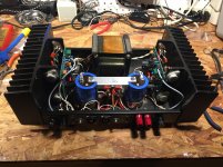
Hooked amp meter across FL 2 to 4. (see attached)
Hooked voltage meter to left speaker post.
Powered on and bulb went bright and settled down quickly as it should. (whew!)
Adjusted bias pot to 230ma and dc to .1mv.
A couple times back and forth and it settled in at those measurements.
Powered it off and waited for the meters to zero out.
Installed both 5A fuses in FL.
Right Channel
DB tester used.
Installed a 3A fuse in FR 5 to 7 spot.
Hooked amp meter across FR 6 to 8.
Hooked voltage meter to right speaker post.
Powered on and bulb went bright and settled down.
Adjusted bias pot to 230ma.
(this is where things go bad)
While adjusting the dc offset, the amp meter clip popped off one side of the fuse holder. I immediately powered down the amp.
Hooked everything up as before and powered it back up. This time the the bulb did not dim as much.
Adjusted the bias to 230ma with no problem.
DC offset; however, will not adjust below -45mv with the pot maxed out. The kit supplier recommends not adjusting more than 25% of center. Its running at about -104mv at 25% of center adjustment.
Does anyone know the consequences of that amp meter clip coming off during testing? Did that take something out?
Any thoughts on how to proceed?
Any help would be greatly appreciated. Was so close!
Anyway.... The rebuild went well on the side my son built and adjusted without a hitch.
Here is the procedure we used:
Left Channel
DB tester used.
Pulled all fuses and installed a 3A fuse in FL 1 to 3 spot.
Hooked amp meter across FL 2 to 4. (see attached)
Hooked voltage meter to left speaker post.
Powered on and bulb went bright and settled down quickly as it should. (whew!)
Adjusted bias pot to 230ma and dc to .1mv.
A couple times back and forth and it settled in at those measurements.
Powered it off and waited for the meters to zero out.
Installed both 5A fuses in FL.
Right Channel
DB tester used.
Installed a 3A fuse in FR 5 to 7 spot.
Hooked amp meter across FR 6 to 8.
Hooked voltage meter to right speaker post.
Powered on and bulb went bright and settled down.
Adjusted bias pot to 230ma.
(this is where things go bad)
While adjusting the dc offset, the amp meter clip popped off one side of the fuse holder. I immediately powered down the amp.
Hooked everything up as before and powered it back up. This time the the bulb did not dim as much.
Adjusted the bias to 230ma with no problem.
DC offset; however, will not adjust below -45mv with the pot maxed out. The kit supplier recommends not adjusting more than 25% of center. Its running at about -104mv at 25% of center adjustment.
Does anyone know the consequences of that amp meter clip coming off during testing? Did that take something out?
Any thoughts on how to proceed?
Any help would be greatly appreciated. Was so close!
Attachments

I would go over and inspect all the connections, solder joints, and then test all the resistors to see if any have drifted.
Might want to order another Qua-Co kit to be able and have a spare set of transistors in case you need them.
Might want to order another Qua-Co kit to be able and have a spare set of transistors in case you need them.
I didn't want to leave this open ended. Phase - Your instinct was correct regarding connections. This ended up being a pinched output wire on the right channel. Qua-co was helpful in helping narrow down the area to look and troubleshooting the resulting issues that came from my careless assembly. The problem was intermittent because it only shorted when the unit would heat up and pinch the wire tight enough to short it out. The moral of the story is... slow down... you will go faster ;-)