Hey,
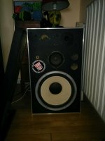
I have a pair of ~30 year old speakers that i inherited, one of which has started to cut out at louder volumes, especially in bass heavy situations.
I have isolated the problem to the internals of the speaker as i tried swapping the units of the two, which made no different.
I wanted to find the part-number of the internals hoping i could find a used pair online, but the crossover seems to be custom made. And i am no expert and would like to restore the pair.
Luckily the crossover does provide quite a bit of information. though i had no luck finding a pre-made crossover with the same specifications
8 ohm
600-5000hz
max effect 40w
L 6db/octave
M 6 db/octave
H 12 db/octave
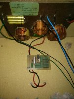
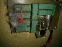
The inside of the speaker contains not only the crossover but a other panel with a bunch of resistors and some other components near the terminal, which has no information on it.
I am hoping some one can shed some light on how i would go about fixing the issue/Restoring the speakers.
~Regards,
Magnus
If any one should be interested the models of the units are the following
Tweeter: Philips ad 1040
Mid-range: Philips ad 50600
Bass: Dantax pf-1220 hrj
I have a pair of ~30 year old speakers that i inherited, one of which has started to cut out at louder volumes, especially in bass heavy situations.
I have isolated the problem to the internals of the speaker as i tried swapping the units of the two, which made no different.
I wanted to find the part-number of the internals hoping i could find a used pair online, but the crossover seems to be custom made. And i am no expert and would like to restore the pair.
Luckily the crossover does provide quite a bit of information. though i had no luck finding a pre-made crossover with the same specifications
8 ohm
600-5000hz
max effect 40w
L 6db/octave
M 6 db/octave
H 12 db/octave
The inside of the speaker contains not only the crossover but a other panel with a bunch of resistors and some other components near the terminal, which has no information on it.
I am hoping some one can shed some light on how i would go about fixing the issue/Restoring the speakers.
~Regards,
Magnus
If any one should be interested the models of the units are the following
Tweeter: Philips ad 1040
Mid-range: Philips ad 50600
Bass: Dantax pf-1220 hrj
Attachments
Last edited:
The close call would be substituting the broken parts in the crossover not all the crossover. To understand how it works Philips has published various 2 and 3-ways that work fine with their classic vintage drivers. The third element or card looks more like a Relay or protection unit. You don't need that to have the speakers in working order.
The close call would be substituting the broken parts in the crossover not all the crossover. To understand how it works Philips has published various 2 and 3-ways that work fine with their classic vintage drivers. The third element or card looks more like a Relay or protection unit. You don't need that to have the speakers in working order.
Thanks for the answer, I might be looking the wrong places, but i cant seem to find the crossovers published by philips, do you by change have a link?
~Regards
Magnus
You probably won't find a pre made crossover the same. If the whole speaker is cutting in and out, it is probably the relay/protection board or the wiring leading to/from it. Maybe that is the intention of the board and there is no problem, but something could be out of spec.
A relay is usually unreliable over time, i'd be looking there first.
A relay is usually unreliable over time, i'd be looking there first.
They are standard crossovers and they were published in book form. I don' have them with me right now. There are some links to some of them (catalogs). It doesn't mean they are the same. A personal project would take to another layout form XO with calibration and all. But, anyway it's not possible to buy a crossover with similar layout in the market because each crossover is made for a special purpose. A crossover only works in the speaker that it was made for or designed for. Difficult to believe but a crossover is not interchangeable with another that is different (just like engines in a car).
Philips Speaker Systems
Philips Speaker Systems
Last edited:
I think what the guys are saying is right, you might as well take out the protection circuit altogether, and be restrained with the volume control. OR renew the capacitor. 😎
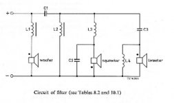
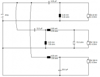
The actual crossover seems simple enough. There is an extra coil not shown. Could be along the lines below.
Troels Gravesen often updates old speakers.
SEAS Kit 503
Those capacitors are getting tired, and are easily enough replaced with new 50V Non-polar electrolytics. The tweeter is probably quite efficient around 92db, and again easily replaced with something newer. WWDT
Only query is whether this is a 4 ohm or 8 ohm speaker. You could measure that. 3 ohms DC for 4 ohm nominal etc. Ha det, as you say!
Attachments
You probably won't find a pre made crossover the same. If the whole speaker is cutting in and out, it is probably the relay/protection board or the wiring leading to/from it. Maybe that is the intention of the board and there is no problem, but something could be out of spec.
A relay is usually unreliable over time, i'd be looking there first.
I took of the board and its says on the back its a 40watt fuse, so i think your correct in assuming this is the problem, and that the fuse in one speaker is not working properly anymore, if i cant find new ones i might just remove them outright.
I think what the guys are saying is right, you might as well take out the protection circuit altogether, and be restrained with the volume control. OR renew the capacitor. 😎
The actual crossover seems simple enough. There is an extra coil not shown. Could be along the lines below.
Troels Gravesen often updates old speakers.
SEAS Kit 503
Those capacitors are getting tired, and are easily enough replaced with new 50V Non-polar electrolytics. The tweeter is probably quite efficient around 92db, and again easily replaced with something newer. WWDT
Only query is whether this is a 4 ohm or 8 ohm speaker. You could measure that. 3 ohms DC for 4 ohm nominal etc. Ha det, as you say!
Does resistors and inductors degrade over time, or only the capacitors?
because i am looking into the replacing the 5 10uf capacitors in each speaker with some new ones from Mundorf as they don't seem to expensive.
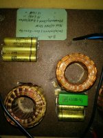
The crossover does contain one component i am unsure of (green square) its simply labeled 4,7/100-A is this a 4,7 uF capacitor or a other type of component?
~Regards
Magnus
4,7/100-A has got to be 4.7uF MKT 100V (Polyester) capacitor.
The rest ought to be 10uF 63V non-polar electrolytics. But conceivably polar wired back to back. You need to work out the capacitor wiring. 2X10uF in parallel makes 20uF. In series 5uF. Three in series, 3.3uF, you follow?
Alcap 50V Standard Electrolytic capacitors for all audio and hi-fi loudspeaker crossover applications.
If the capacitor on the relay has deteriorated, because wet electrolytic dries out over the years, it would make the diode rectifier trip sooner IMO.
Changing non-polars to Mundorf MKP (polypropylene) might make the speakers overly bright.
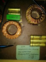
Those metal can capacitors, although they may look like the infamous aluminium electrolytic capacitors at first sight are in fact metallized polyester dielectric. Searching
"MKT1813" brings up this datasheet from Vishay:
http://www.vishay.com/docs/26013/mkt1813.pdf
These are unlikely to go bad and are actually a good choice for a crossover (compared to electrolytic). The reason they are "polarised" is because the outside metal can is connected to the end with the band. This is a useful feature for RF suppression and shielding but is of no significant importance for a speaker. They work just as well for AC applications. Looks like whoever built the speakers sprung for premium heavy gauge air core inductors as well.
The green 4.7/100 component is probably a metallized plastic film cap too. Likely 4.7uF, 100V.
Like others have said, the problem is likely to be on the protection board with the relay. Maybe the relay itself, or if that silver can is an electrolytic capacitor, maybe that. If you are extremely unlucky, one of the power resistors on that board may go open circuit when it heats up. Hard to say without having the schematic. A quick fix would be to simply bypass the board and resist the temptation to turn up the volume too much.
Last edited:
4,7/100-A has got to be 4.7uF MKT 100V (Polyester) capacitor.
The rest ought to be 10uF 63V non-polar electrolytics. But conceivably polar wired back to back. You need to work out the capacitor wiring. 2X10uF in parallel makes 20uF. In series 5uF. Three in series, 3.3uF, you follow?
Alcap 50V Standard Electrolytic capacitors for all audio and hi-fi loudspeaker crossover applications.
If the capacitor on the relay has deteriorated, because wet electrolytic dries out over the years, it would make the diode rectifier trip sooner IMO.
Changing non-polars to Mundorf MKP (polypropylene) might make the speakers overly bright.
Thanks, ill be ordering some new capacitors from the link you provided. (The description even says they sound like the ones used by most manufactures in the 70-80, where these speakers are from)
I've also decided to remove the relay completely as the speakers are rated
150w sinus power
250w music power
4-8 ohm
and my receiver is rated 150w 6 ohm, so i don't think ill be in danger of blowing the speaker250w music power
4-8 ohm
~ Regards
Magnus
Those metal can capacitors, although they may look like the infamous aluminium electrolytic capacitors at first sight are in fact metallized polyester dielectric. Searching
"MKT1813" brings up this datasheet from Vishay:
http://www.vishay.com/docs/26013/mkt1813.pdf
These are unlikely to go bad and are actually a good choice for a crossover (compared to electrolytic). The reason they are "polarised" is because the outside metal can is connected to the end with the band. This is a useful feature for RF suppression and shielding but is of no significant importance for a speaker. They work just as well for AC applications. Looks like whoever built the speakers sprung for premium heavy gauge air core inductors as well.
The green 4.7/100 component is probably a metallized plastic film cap too. Likely 4.7uF, 100V.
Like others have said, the problem is likely to be on the protection board with the relay. Maybe the relay itself, or if that silver can is an electrolytic capacitor, maybe that. If you are extremely unlucky, one of the power resistors on that board may go open circuit when it heats up. Hard to say without having the schematic. A quick fix would be to simply bypass the board and resist the temptation to turn up the volume too much.
Might have to take a second look before purchasing new capacitors then, but yes i will be bypassing the relay completely. and i Don't think my receiver is powerful enough to blow these speakers (see my reply above)
~Regards
Magnus
A quick question if were going to replace them would you recommend anything specific? or will the Alcap linked by system7 work fine.
The problem with power is not the woofer generally speaking, is the mids and tweeters that can't accept W by the "dozen"...
Pay care that a crossover when it fails, a lot can go wrong with the drivers and other passive components. Maybe that's the label written saying "Max. 40W" meaning something like to be careful?!
Pay care that a crossover when it fails, a lot can go wrong with the drivers and other passive components. Maybe that's the label written saying "Max. 40W" meaning something like to be careful?!
Hi,
Swap the relay board between speakers to see what happens.
If the problem moves, start swapping relay board components.
rgds, sreten.
Swap the relay board between speakers to see what happens.
If the problem moves, start swapping relay board components.
rgds, sreten.
The tweeter and mid are rated 40w (http://www.cieri.net/Documenti/Altri marchi/Philips - Speakers (1970~1980).pdf), same value written on the crossover and on the back of the relay panel. i don't know the rating of the woofer, but the label on the back of the speaker readsThe problem with power is not the woofer generally speaking, is the mids and tweeters that can't accept W by the "dozen"...
Pay care that a crossover when it fails, a lot can go wrong with the drivers and other passive components. Maybe that's the label written saying "Max. 40W" meaning something like to be careful?!
150watt sinus power
250watt music power
You mean the whole boards? Sounds like a plan, but System7 seems to be on to the issue.that the fuse in one speaker is not working properly anymore, if i cant find new ones i might just remove them outright.
Resistors and inductore usually last unless they are damaged by heat. This is sometimes obvious by discolouration but this can be hidden inside inductors. Usually they are ok.Does resistors and inductors degrade over time, or only the capacitors?
This won't help much and if you decide to run without the protection boards you may need to rely on your ears to detect any distortion from overdriving them.The tweeter and mid are rated 40w
Fuses can look good but have poor contacts where they are installed. Better to bypass or upgrade to thermistors for instance. And with regard to your amplifier: small amps are very good at toasting tweeters.
As TMM said earlier, because he looked them up, all the capacitors all seem to be MKT polyester. I wouldn't even replace them. They are near indestructable. And quite decent quality.
The relay rectifier cap, well, we don't know...or for that matter, the whole protection circuit. But worth reflowing the solder on the circuit. Joints fracture over time with vibration.
The relay rectifier cap, well, we don't know...or for that matter, the whole protection circuit. But worth reflowing the solder on the circuit. Joints fracture over time with vibration.
Hey Magnus,
Did you get your crossover layout already? 😀
Here a different XO design layout, with PTC (protection) for Philips drivers, that I found, you will find it interesting to learn.
PHILIPS FB815 Crossover schematic by Kiriakos GR
2014 Speakers PHILIPS FB815 Digital, ready for foam surrounds replacement
Did you get your crossover layout already? 😀
Here a different XO design layout, with PTC (protection) for Philips drivers, that I found, you will find it interesting to learn.
PHILIPS FB815 Crossover schematic by Kiriakos GR
2014 Speakers PHILIPS FB815 Digital, ready for foam surrounds replacement
Try cleaning the relay contacts by sliding a piece of copy paper carefully between the closed contacts. The clear cover should pop off.
If that doesn't work, bypass that protection board. Actually, I'd do that first and not worry about the relay contacts.
The crossover looks fine if all joints are intact.
Total dropout points to the relay in my reading of the scenario.
If that doesn't work, bypass that protection board. Actually, I'd do that first and not worry about the relay contacts.
The crossover looks fine if all joints are intact.
Total dropout points to the relay in my reading of the scenario.
- Status
- Not open for further replies.
- Home
- Loudspeakers
- Multi-Way
- Need some help restoring vintage speakers