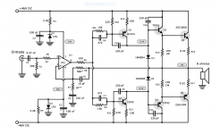
How does this schematic amplify aboce the OP amp rails ?
2sa1015 / 2sc945 amplify voltage ?.
In LTSpice for 35-0-35 rails i have to increase R10-R11
Also why is there such big caps like 330pF from base to emitter on the TIP's, wouldnt 100-200pF will be enough ? .
Can you explain why is there R8 -C6 R9-C7 between the bases of 2sa1015 / 2sc945 and the op amp's output. I dont really understand this schematic.
It would be " better " than what I wanted to build, because I can get more power , Im not limited to the Op amp's rails , I have 2sa1015 and 2sc1815
and for op-amp I have: TL072 - NE5532 or I can buy something else , I dont own TIP42-41 I tought i can use BD139-140.
Also Why is the OP-amp used in inverting input ? .
Thanks again, Sorry for so many questions .
Attachments
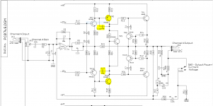
Yes it will swing outside the rails. Having the collectors of the Q1 Q2 tied to the diode spreader stack is not how Marshall 8008 & Peavey PV-4C do it. They tied the emitters, collectors go to rails. Same number of parts, but they make money and this amp didn't.
Thread Peavey PV-4C
PV-4C Schematic:
http://music-electronics-forum.com/attachments/17318d1329063473-pv-4c-schematic.pdf
Marshall 8008 schematic http://www.drtube.com/schematics/marshall/8008.pdf
Having the feedback go to the op amp plus input is how marshall 8008 does it.
R8-C6 R9-C7 separate the voltages for Q1 & Q2 so they can tie the emitters to two different voltage sources, the rails. So the whole stack moves up & down together.
On PV-4C, the analogos transistors are Q100 and Q104 (page 3).
I'm using mps8098/99 or MPSA06/56 for this TO92 predriver instead of those phillips numbers. Phillips is unavailable here, and the ****ese copies are hit and miss on the specs. Many ****ese copies I get from farnell or digikey, the manufacturer doesn't even issue a datasheet, they just reference the Phillips or Toshiba one. For more power rating in TO92 there was a 1 W MPSW06/56, I've got a hundred of the 55's. There are Zetex/diodes inc 2n6716/6727 in 1 W package if you can get those easier. pn3904 & pn2222 are a too light on the Vceo rating for 35 v rails IMHO.
In the PV-4c schematic U100B is the op amp stack driver. You can see pins 1 & 2 from the output board are the double diode stack. That is so the diodes can be over on the heat sink.
Ignore Q102 Q103 CR106 CR112 on the Peavey, those are the VI limiter which you don't need if you're not performing on stage.
BD139-140 can work as drivers but they are light on the power rating, be sure to put a heat sink on them. The Phillips ones will produce better extreme highs than TIP41/42, but the fairchild BD139/140 I can buy are not necessarily faster than TIP41/42.
Any semi-complementary output transistor will work, they are just emitter followers. The more modern ones have better gain at high currents. I can get cheap ON semi parts like MJ4302/4281 or MJL21193/4, Europeans seem to get better prices with 2SA1943/2SC5200.
For sure don't bother with a 741 op amp, they are hissy. Any of the others you have in stock are better.
Compensation cap is IMHO to taste. I put smaller disc caps in which I can parallel with something the same size if I need more due to oscillation. I would think those 330's would limit high frequency response. Funny place to put them, too. I'd start with 47 or 68 pf there to see if the design would get away with it. Putting phase compensation back on a single VAS transistor is an advantage of those designs. All the way out on the drivers is old hat.
I am a builder, not a simulator. I bought a radio shack grab bag in the seventies, I have a lot of values of disk caps. Some surplus house like electronic gold mine has more the same assortment of values these days. Don't buy surplus electrolytic caps, the rubber expires on the shelf. the RadioShack disk ones from the 70's seem fine, although marking is sometimes inscrutable.
Last edited:
On the circuit in post 61, R8 C6 C8 R10 R9 C7 C9 R11 may oscillate internally. Too many springy things (capacitors) all tied together. That may be the reason C10 C11 have to be so huge, to damp all that mess out. Imagine a network of springs (capacitors) and shock absorbers (resistors). If you wiggle 6 springs from the middle, they are likely to make a humming noise (oscillation) at their own higher frequency.
With the emiiters of Q1 Q2 tied together instead of collectors, the number of capacitors decreases and less chance of a oscillating mess.
C104 & C113 of the PV-4C tied BC of Q100 Q104 are much simpler.
With the emiiters of Q1 Q2 tied together instead of collectors, the number of capacitors decreases and less chance of a oscillating mess.
C104 & C113 of the PV-4C tied BC of Q100 Q104 are much simpler.
With regards to your previous pic (you deleted it):
I can't say for 100% certainty, but just check the values of R8 and R9 - you're pushing more than half a watt on Q1 and Q2, and you might encounter thermal runaway. You can probably make R8 and R9 560 ohms to bring the power down, and make that stage a bit more thermally stable. Still, I would strongly suggest using a current source and not a resistor. Something like this:
I can't say for 100% certainty, but just check the values of R8 and R9 - you're pushing more than half a watt on Q1 and Q2, and you might encounter thermal runaway. You can probably make R8 and R9 560 ohms to bring the power down, and make that stage a bit more thermally stable. Still, I would strongly suggest using a current source and not a resistor. Something like this:
An externally hosted image should be here but it was not working when we last tested it.
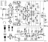
Also found this one, very simillar , but why is there no cap for each T1 and T3 and only one 470p from their bases trough R11 - R12 and than to collector , does this make it economical than using two caps for each transistor's B-C .
Now I understand what T1 - T3 does after the op amp, T2 is an vbe multiplier ( or how is it called ) instead of biasing diodes, but what does T4 -T5 do there? also mje15030/mje15031 dont need cap from Base to Collector ? for stability / oscillations?.
D15 and D16 are used for electrostatik discharge or something like that ?.
D3...D6 what are they for ?. Thanks again.
Attachments
Last edited:

Thank you Mrcloc , I have some nasty experiences with constant current sources , but I will try.
Thank you Mrcloc , I have some nasty experiences with constant current sources , but I will try.
Nastier than 13 stabilizer capacitors? 😀
The only thing about my current sources is that it might be a class B stage, where you shouldn't use a current source, and the 1k resistors actually create the amplification. Either way, the 100 ohm resistors seem a bit small in my opinion.
I can't really analyze the circuit in post 67 now, but I'll try have a go later.
I mean it could be that Q1 and Q2 make a class B VAS (although it's biased, it's not necessarily a push-pull). I don't know. Like I said - I can't do much analyses now, and I'm not too familiar with this layout. Have a look at this awesome Class B design to see what I mean - the class AB stage can only do a small output current, and then the class B output stage takes over when the class AB stage current is large enough to overcome crossover distortion.
Having a closer look - it's actually a class A stage like any other normal VAS.
Having a closer look - it's actually a class A stage like any other normal VAS.
And being a normal class A, it's best to leave out Q4 and Q9. Make R8 and R9 560 ohm each, and you'll still have enough current.
ok , thank you. Do i really need BD's there or I can use small complementary like BC559-549 or so ?.
You're going to definitely need something that can be mounted on a heatsink.
And good luck with your oscillator~~~~~~~~~~! 😀
And good luck with your oscillator~~~~~~~~~~! 😀
Im building to learn , and for fun . Why you say it is an oscillator ? 😀 , can i fix that? .
In Simulations it doesnt oscillate
In Simulations it doesnt oscillate
What op amp are you simulating with? I can't get it to not oscillate. Why do you think they use that many capacitors in similar designs? It's just so easy for these to oscillate. Do you have an oscilloscope? Sometimes the oscillation is high frequency and only causes a hiss in the speaker.
I've seen many (very rugged) output devices go up in smoke due to oscillations (with no load!).
I've suggested it before - use a simple discrete design for more power. Try a very simple op amp design to learn. The thing is that you can't easily calculate the S parameters for such a circuit because you never know exactly what's going on inside the op amp.
I've built two guitar amplifiers on an identical PCB with identical components. One oscillated and one didn't. The only difference was a slight wiring difference in the power supply (longer and shorted wires). Oh, and different guitar cables. I switched to a discrete preamplifier, and all oscillations were obliterated.
I'm also a noob with op amps, but only because you need to really know what you're doing with them, and that takes experience. I can design excellent theoretical op amp circuits. I just find it much easier to stick to discrete where I know exactly what's going on, and I get the same noise and distortion figures, and I need no fancy power supply, and simply use the main rectified power supply. It's just a win all around. Even a Baxandall implementation with discretes is a simple matter. I'll see if I can find a simple discrete preamplifier here at work (I might just leave out the Baxandall part because I don't quite have the time to put it in now).
If you really want to learn op amps, look into instrument amplifiers and low voltage preamplifiers. You can also look into switching power supplies using op amps.
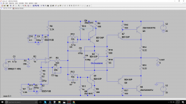
Something like this. Now this isn't 100% - it's something like the preamp I'm busy with, but tell me this isn't simpler than an op amp circuit. For best results, use 1% 0.5W metal film resistors and BC550/BC560. This circuit's performance will be exceptional.
An externally hosted image should be here but it was not working when we last tested it.
- Status
- Not open for further replies.
- Home
- Amplifiers
- Solid State
- Need some help :D