BTW, if you had built a chip amp you would never have learned this thing about the diode voltage sagging as they heat up, and the model of the two junction darlington transistor modelling two diodes. See, DIY is worth it especially when it doesn't work right at first. Expands your knowledge.
Couldn't agree more!
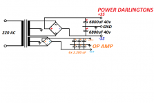
Hello again, yesterday I winded another secondary on my Toroidal transformer. It had 2x 26.5v AC , and I made another 2x 16v AC . and I used the two 26.5V ac ( 36v 0 -36v DC) for the darlingtons and the new winding ( 22.5 0 -22.5 DC )for the OP-AMP. And it doesnt work , I have DC on the output.
1AMP Bridge Rectifier, 2x 15 mH coils for ripple !? and 5.400uF per rail for the op-amp
Here is the schematic:
1AMP Bridge Rectifier, 2x 15 mH coils for ripple !? and 5.400uF per rail for the op-amp
Here is the schematic:
Attachments

Last edited:
I'm going to guess that C2 prevents a DC ground reference point? But let me look at it more and see if I can see something.
Or there's something not quite right with the power supply? Perhaps post your power supply schematic?
Very creative. Been thinking about winding extra winding on a toroid for other voltages, myself.
Op amp DC offset will be magnified by the gain & push the output to DC one way or the other.
Between C2 & R3, put the wiper of a 100k pot. Put one end of pot to +22, other end of pot to -22. Adjust until the output of op amp is in the middle, 0 v.
And or decrease R4 to provide more centering feedback.
Because you used darlington emitter follower output transistors, the speaker output won't go outside the max excursion of the op amp, minus 1.2 v each end. That's about 18/1.4 or 12.5 vac, which would provide a lot of power anyway on a 8 ohm speaker. Op amp will swing 22-~2.5 v or 19.5, - 1.2=18.3 peak volts out. Vpeaktopeak/1.4=Vrms
Last edited:
Between C2 & R3, put the wiper of a 100k pot.
I concur.
I think you could also put a 100k in parallel with C2 and R3 to cause a low DC gain (2?).
An externally hosted image should be here but it was not working when we last tested it.
*Sigh* - op amp based amplifiers. They always have issues. And having two separate power supplies might give you an unacceptable level of hum. Ground loops are quite a thing to sort out, now you have two possible sources of ground loops.
Last edited:
1) +/- 22.5V rails will *destroy* any Op Amp, period.
2) that´s a very poor design, power transistors will "follow" whatever the Op Amp sends them, so you are wasting the +/-35V rails.
3) I suggest you build a tried and true circuit.
With Op Amp front end if you like that, but properly designed.
This one is somewhat poor, yet 100 times better than the one posted above:
CONSTRUYA SU VIDEOROCKOLA.COM > Descargar PDF del amplificador mono de 400w
2) that´s a very poor design, power transistors will "follow" whatever the Op Amp sends them, so you are wasting the +/-35V rails.
3) I suggest you build a tried and true circuit.
With Op Amp front end if you like that, but properly designed.
This one is somewhat poor, yet 100 times better than the one posted above:
An externally hosted image should be here but it was not working when we last tested it.
CONSTRUYA SU VIDEOROCKOLA.COM > Descargar PDF del amplificador mono de 400w
It's better, but very similar. The major difference I can see is the current sources in the driver.
Either way, it's still way more complex than a simple discrete design which can perform better and tolerate higher voltages.
Either way, it's still way more complex than a simple discrete design which can perform better and tolerate higher voltages.
Thank you for the sugestions , I will try them tomorrow. Hope it solves the problem.
Also I fried the TIP's...( Noob forgot to check the bias pot , and it was set too high ).
I will try some CFP made with BD139-BD140 and 2sc-2sa power outputs.
Also I fried the TIP's...( Noob forgot to check the bias pot , and it was set too high ).
I will try some CFP made with BD139-BD140 and 2sc-2sa power outputs.
But when the amp was supplyed with 20-0-20 V ( the op amp from the same rails ) it didnt do this : " Op amp DC offset will be magnified by the gain & push the output to DC one way or the other. "
This happend because Now I use separate power for op amp ? .
This happend because Now I use separate power for op amp ? .
No! I've turned many transistors into smoke. Some quite dramatically. Use TIP35/6C.... They are ROBUST! 😀 (Although I've taken many of those down anyway)
CFP can oscillate EASILY. I use a capacitor for BC junction on the driver transistor, and I also provide a ground path via capacitor from the VAS. This is not a Miller capacitor, so the value isn't that small - around 560pF. I would suggest using a darlington first. I've had excellent results with darlingtons and no thermal stability issues, provided you put the diodes into thermal contact with the output. When I say darlingtons, I mean a darlington configuration, not the monolithic darlington.
If you want to use some nice monolithic darlingtons, BDW93/94 are very nice (also cheap).
Using two supplies - you may end up with some (small) DC offset due to no DC reference point in the feedback loop. Not sure where the problem is though.
I can make a " darlington from BD139-140-TIP35-36 , would adding resistors form base to Emitter improve speed ? how do I connect them .
I need to try what Indianajo said , beacause i have problem with DC offset being a few volt 7-8 V or so .
But i have some 2sc-2sa rated at 100W / 15A collector and i had " drained " 150W of each pair NPN-PNP ( with distortion ) but without blowing them.
I need to try what Indianajo said , beacause i have problem with DC offset being a few volt 7-8 V or so .
But i have some 2sc-2sa rated at 100W / 15A collector and i had " drained " 150W of each pair NPN-PNP ( with distortion ) but without blowing them.
I can make a " darlington from BD139-140-TIP35-36 , would adding resistors form base to Emitter improve speed ? how do I connect them .
I need to try what Indianajo said , beacause i have problem with DC offset being a few volt 7-8 V or so .
But i have some 2sc-2sa rated at 100W / 15A collector and i had " drained " 150W of each pair NPN-PNP ( with distortion ) but without blowing them.
Someone else can answer this.
All I know is that the 35/6 make good outputs. I always used MJE340/50 because I never really liked the BD139/40, but many do like them.
For +-22V, you're only looking at about 25W in 8 ohms, and for that, TIP41/2 are also fine. But there are probably better "audio" transistors that others will recommend. I don't know about those 100W 2sa/c's.
I've used TIP41/42C for drivers in my AX6. They are just a little bit slow on tinkly bells, otherwise sound fine. Ft=3mhz.
I don't know why all this thrashing around with op amps. Educational, but meanwhile I'm listening to my AX6. That schematic JMFahey posted would work but has same number of transistors as an AX6 plus an op amp. The drivers & 2sc 2sa output you have are probably fine, you need a E.20 2n5401 for the input and assortment of 270k to 2m resistors to set the operating point in the middle of the rails. You need a 2sc5200 pair for output, or mj4281 or MJW3281 or even TIP35 as the man said. NPN outputs, it is quasi comp.
If you really want to do op amp. forget the darlington output and copy something commercial like a Peavey PV-4c , Peavey Basic 50, or marshall 8008, leaving out all the frills like DDT, VI limiter, frequency filters in the guitar amps, etc. All these schematics are on the net. All have one set of TO92 predrivers after the op amp and before before the driver & output transistors.
One tip on not blowing outputs due to excessive bias. Parallel the bias adjust pot with a .7 v rated diode, so voltage drop can't go more than that. Like 1n4148.
Last edited:
Mr Rod Elliot's Project76 uses separated power supply for OP-amp and Output transistors and he doesnt have the problem with DC offset.
Maybe when the TIP's died they fried something else on the board as well , I have to take a look ( the bias pot was set to high and i forogt , and the TIP's Fried )
Opamp Based Power Amp
Maybe when the TIP's died they fried something else on the board as well , I have to take a look ( the bias pot was set to high and i forogt , and the TIP's Fried )
Opamp Based Power Amp
- Status
- Not open for further replies.
- Home
- Amplifiers
- Solid State
- Need some help :D