I feel Jaycee and ketje are completely wrong. I can't believe that piece of trash that turns on the output transistors with the power supply current to the op amp, resurfaced.
To build a chip amp you have to have a chip amp IC.
Chip amps cost me a $10 freight bill plus IC cost of $7 up. Op amps are <$1 and TIP142/147 are just above $1. The diodes are $.07 and the resistors are $.20. Maybe freight will cost you more since you don't live 8 miles from a UPS air hub. And I have commercial destination status, avoiding the "house delivery" charge. You don't learn as much on the chip amp, either.
Thousands of commercial amps use an op amp as the input stage. Most are using drivers and separate output transistors, but it could be done with darlingtons. PV4c is one. Leave out the VI limiter parts, you aren't playing on stage on temporary cables.
You need to put the diode stack near the output transistors. This makes the voltage collapse as the diodes heat up, slowing growth of idle current in the outputs. I have my diodes on the AX6 board mounted above the output transistors on the heat sink. More ideally there are epoxy compounds containing berylium oxide that can glue the diodes to the heatsink. I don't have a brand name, but it is NOT artic silver which contains a conductor, metallic silver.
Vbe multiplier can work but you can't drive it in the middle. Follow the instructions in post 4 or 6.
You have to match the size of the pull up pull down resistors on the diode stack, to the output current safe limit of the op amp.
Because of the double diode drop in darlingtons, you need 4 diodes in the stack or follow the instructions about combining 3 diodes plus a schottky plus a variable resistor which will be replaced by a fixed resistor after prototyping.
Last edited:
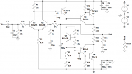
I have some questions about the schematic bellow.
Since the "output stage " uses darlingtons and not drivers and power output transistors ( for thermall stability they must have been put on the same heatsink ). Just the TIP142-147 on the heatsink would be ok ? no thermall runaway ? Do i need to put the bias diodes on the Heatsink as well ? or replace them with a Transistor which i put on the heatsink ?.
Do i need to add a zobel for stability ?
50-100p caps between the base and collector of the TIP's for oscillations ?.
Thank you.
In my experience, I recommend against this circuit. A few issues:
1. The output resistors are small, so your bias current is going to be fairly large, and you will have thermal run away quite quickly.
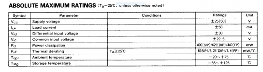
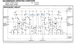
2. These circuits don't last long. If you read the manufacturer datasheet for op amps, you will find most can only do +-18V, and an NE5532 can do +-22. This doesn't mean they can sustain this. They recommend for NE5532 +-15V.
3. These circuits don't sound great. They really don't, and they're intolerant of varying loads. The 4.7k resistors are not suitable as current sources for drive current, and the op amp can't drive much current either. Using the TIP142/7 mitigates this a bit, but still.
4. A simple pentawatt package chip amp works much better. Say what you want about chip amps, but they do work, and they sound good in normal operation.
Furthermore, chip amps also provide protection circuitry, which is a good thing. With that schematic, and the 0.22 ohm outputs, if you short the output, the amp is a gonner.
If you wish to build a similar circuit, a few things I can say will do well are:
1. Add a proper current source driver stage.
2. Use discrete parts for the output - Sziklai outputs work like a charm for small power and simple design.
3. Use a proper bias servo.
4. Use <= +-15V regulated supply.
5. Drive low impedance speakers.
You'll get a useful 10W for 8 ohms. A Zobel is always highly recommended. I mean, why leave it out? It's such a simple thing. And then ask yourself the question: is it really simpler than a normal discrete amplifier?
Attachments
I am using Mitsubishi 5220 ( +-25v MAX ) 22.5v recommended , My power supply is +- 20.5v so no problem , Tried NE5532 on , but it got a little hot .
It works fine.. but i get only 11v output without Clipping , the NE5532 says it's output is 32v peak to peak at +- 18 , 600 ohm load, that would be 15-16v , and I get only 11 v with it , at 20.5v rails.
Had a problem with thermal runaway when no speaker was on , but with a zobel it fixed it.
100mA quiss on the TIP's , I have a decent heatsink with a fan it runs cool.
I only made a channel yet to test, on my " Tower " speakers in parralell , 3 Ohm.
on music it distorts after 8-9 V , and on a sinewave 30 - 40 hz i get 10v without distortion, this is weird.
If it is the cicuit from post 1 that's normal.The driving current for the darlingtons doesn't come from the opamp but from R5 and R6.More output voltage = less for R5 or R6 = less drive current just when you need more.I am using Mitsubishi 5220 ( +-25v MAX ) 22.5v recommended , My power supply is +- 20.5v so no problem , Tried NE5532 on , but it got a little hot .
It works fine.. but i get only 11v output without Clipping , the NE5532 says it's output is 32v peak to peak at +- 18 , 600 ohm load, that would be 15-16v , and I get only 11 v with it , at 20.5v rails.
Had a problem with thermal runaway when no speaker was on , but with a zobel it fixed it.
100mA quiss on the TIP's , I have a decent heatsink with a fan it runs cool.
I only made a channel yet to test, on my " Tower " speakers in parralell , 3 Ohm.
on music it distorts after 8-9 V , and on a sinewave 30 - 40 hz i get 10v without distortion, this is weird.
Try my circuit 😀
Mona
Actually AC current would very much be coming from the opamp, that's what the electrolytics in parallel to the biasing are for. Either they were left out, wired in wrong or the opamp ran out of steam.
9Vp into 3 ohms is 3 A peak, wouldn't be surprised if beta on the Darlingtons took a nosedive at this point. The datasheet says beta >1000 at 5 amps though, so we should only be looking at a few mA max at this point.
Output amplitude with music being smaller than on a bass sine wave is very suspicious though. Something is seriously going wrong there.
What's the power supply looking like? Is there decent supply bypassing?
Like I say, in real life, these op amp amplifiers aren't great for driving speakers decently. And they're really just more complicated than a simple discrete amplifier. The winner for simplicity is a chip amp.
I've built many op amp amplifiers, and they just never work well (follow simulation or theory), they don't ever sound fantastic, and they end up being more complicated with all the bypassing, biasing, etc.
I've built many op amp amplifiers, and they just never work well (follow simulation or theory), they don't ever sound fantastic, and they end up being more complicated with all the bypassing, biasing, etc.
I own two op amp driven amplifiers. Both sound excellent.
Both are commercially designed & built. Both use triple discrete parts, predriver, driver, output transistor. Both have VI limters and complications like excessive high frequency detection and reduction.
Both have adequate spreader voltage around the drivers to eliminate crossover distortion.
Personally I measure output watts with an analog VOM. More consistent readings are given on resistors instead of speakers. On actual music my two DVM give random numbers. DVM are designed to measure sine waves out of the wall plug. Except the RMS capable Fluke meter, which is not capable of detecting oscillations above 7 kz. My VOM is capable of detecting some Mhz of AC oscillation 50 mv & above. Analog VOM require a capacitor in series with the probe to block response to DC voltage. Except those VOM with a "RF probe" with the internal capacitor.
Last edited:
To build an amplifier using an op amp as an integral part to achieving something specific (like the Apex B500), where the complexity is a sure bet, I'm all for it, but it does require a lot of design.
These quick op amp "make it easy" amplifiers (with little to no design) are what I'm referring to.
These quick op amp "make it easy" amplifiers (with little to no design) are what I'm referring to.
2x 6800 uF on the power rails , 10A bridge rectifier, 100n F 5mm close to the OP AMP , and 2x 1000uf on the board .
If the 1000 uf caps are the supply rail caps for the op amp, 1000 uf is fine.
If the 1000 uf caps are the idle current stabilization caps across the diode stack, that is a bit excessive. The idle current won't follow the music very well. 100 uf or 22 uf is more traditional.
The bias being correct requires the pot to bring the voltage up near 2.2 v or 2.4 v for complementary darlingon output transistors. Or sgskloss idea of increasing the diode stack to three 1n4148 and a zener, plus a 100 ohm pot. If there is too much pot and not enough diodes, the voltage won't sag much as the heat sink heats up. (the output transistors Vbe voltage does sag as they heat up).
In terms of available cheap parts for the diode stack, 1n4148 typically read about .7 volts drop (700 ohms on the 2000 ohms scale of a DVM). The fatter diodes out of a dead PCAT power supply, or dead CRT monitor switcher supply, will read more like 400 ohms to 480 ohms. These allows you to creep up on 2.2 v output idle current spread gradually by adding diodes, instead of requiring a schottky at the end of three 1n4148. Single schottky's are hard to find in salvage, without orderin a part from a distributor. You can find schottky's in duals in dead switcher supplies, and only use 2 legs of the three. Schottky's read about 150-180 ohms on the 2000 ohm scale.
Like sgskloss, I don't think the ground connection at the middle of the diode spreader stack adds anything, so the second voltage spreader capacitor is redundant.
The connection between op amp and speaker through a resistor in post 12 is fine for a headphone amp, but using a 600 ohm drive op amp like 5532, and a 40 W rated 4 ohm speaker, produces almost no volume. Somebody installed that resistor for a TDA7294, a 68 ohm 5 watt. TDA7294 is a trouble prone chip amp of 5 amps out, and resistor connection seems effective with the pass transistors driving output up to 400 W, accordging to that thread.
Last edited:
1000uf are supply rails + 6800 on the " power supply board ".
I have used 220uF for "the idle current stabilization caps across the diode stack"
I had a problem, set quiss current to 100mA without speaker, when i connected speaker it got down to 0, changed it again with the speaker to 100mA , dissconected the speaker it jumped to 200 and keep rising, I put a " zobel ? " 10 ohm resistor in series with 100nF cap between output and GND and it solve it .
The amp works fine, I noticed that the diodes when they warm up the quiss current rises , when they are cool it goes back to the " value set " , I put the 1n4148's on the heatsink ( it doesnt touch the heatsink ) but the fan cools down them and the heatsink it self, but i notice if I listen to 3/4 power after pausing the music the quiss current rises to 300 mA or soo ( THE heatsink is cold-warm ) and in a few seconds it goes back to 60-100mA , I think the diodes warm even if the heatsink is cold and this rises the current ? correct me if Im wrong .
Actually if the diodes warm the voltage should drop and the idle current should drop. Voltage across silicon diodes goes down as the temperature goes up. Same as the output transistor Vbe.
Fan blowing on the diodes is bad. They will cool easier than the heat sink. Put a blob of heat sink grease on them to couple them to the heat sink, and block the air flow IMHO. Lacking that, petroleum jelly.
As far as measuring, I find when the music is on I get redicululous values for the voltage on the upper emitter resistor, which is how I measure idle current. Poor measurement method for idle current. When music is flowing current goes out to the speaker, so a differential measurement of current would be required, emitter resistor current - speaker current, which I don't have enough fancy equipment to do. So I don't worry about it.
Last edited:
in the early 70's I made several op-amp amplifiers for my self and for friends who didn't have much money. I powered the output darlingtons (MJ2501/Mj3001) with a higher unregulated voltage. I used zener regulators for the opamps and ran the op amps at the max rated voltage of +/22 volts with tiny heat sinks glued to the top of the opamps. I know it is bad design but most op amps will run at a higher than normal supply voltage if you do not exceed the maximum power levels and keep the output current below max drive capabilities.
But why then, with the diodes in air i touched them with my hand ( i had cold hands ) and the current droped down.. So it's the other way. I tought why do they put diodes , on the heatsink if hotter temp makes them rise current even more.
Ok i wil try that, thanks.
Something weird that crossed my mind, can you use a transistor like a diode ? B-E for example ?
Ok i wil try that, thanks.
Something weird that crossed my mind, can you use a transistor like a diode ? B-E for example ?
B - E, is sort of a zener diode, voltage drop ~7V.I know its not economical , Im just curious
B - C, a diode with max current= base current
B and E together - C, is an allmost (not quite) saturated transistor
Mona
The reason sgskloss told you to put four diodes in series instead of two, is that you get voltage drop FOUR TIMES when the diodes heat up. So you get about twice as much voltage drop hot with four diodes instead of two. This follows the four junctions of the two darlingtons as they heat up, better than two diodes. The ground in the middle of the two diodes on the original design is redundant. Follow post 6.
My idea of four .48 v diodes from salvage switchers gets you there easily, sgskloss idea of 3 1n4148 plus a schottky diode gets you there. With four 1n4148 you probably have too much voltage spread, 2.8 v. Three 1n4148 plus a series pot at least gets you 2.1 v spread and three diode drops sagging as they heat up.
Pansote used some bd139/140 as diode heat sensor, he had to insulate the heat sink from the output transistor heat sink with mica to screw it down on top. And you have to use the junction forwards for it to act like a diode.
BTW, if you had built a chip amp you would never have learned this thing about the diode voltage sagging as they heat up, and the model of the two junction darlington transistor modelling two diodes. See, DIY is worth it especially when it doesn't work right at first. Expands your knowledge.
Last edited:
- Status
- Not open for further replies.
- Home
- Amplifiers
- Solid State
- Need some help :D