I have some questions about the schematic bellow.
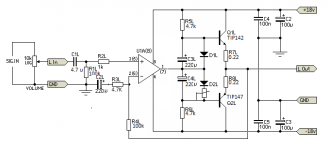
Since the "output stage " uses darlingtons and not drivers and power output transistors ( for thermall stability they must have been put on the same heatsink ). Just the TIP142-147 on the heatsink would be ok ? no thermall runaway ? Do i need to put the bias diodes on the Heatsink as well ? or replace them with a Transistor which i put on the heatsink ?.
Do i need to add a zobel for stability ?
50-100p caps between the base and collector of the TIP's for oscillations ?.
Thank you.
Attachments
Last edited:

> 50-100p caps between the base and collector of the TIP's for oscillations ?
No. These are emitter followers. A cap there would just annoy the opamp.
> no thermall runaway ?
If the un-specified diodes are single diodes, it will never run-away.
Unless the un-specified bias trimmer value is set too high!
With some assumption about that un-specified bias resistor, the output stage will run stone-cold, with measurable crossover, greatly masked by opamp gain. I have seen/heard stages like this work "well". But it is not a "fine" design.
Build it. Simple, and doesn't cost much.
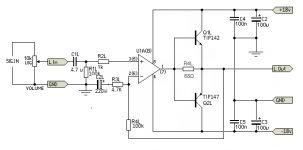
Add another regular diode in series with D1L, maybe a Schottky in series with D2L, mount all the diodes on the heatsink with the Darlingtons, and see what kind of idle current adjustment range you get. I don't think the pot needs to be much over 100 ohms.
BTW, in sim I have never seen much difference between the two electrolytics as shown and just one electrolytic between the two bases. Might save some space.
Since nominal supply is reasonably high as-is, I would also consider moving the opamp connection up to Q1L base while omitting R5L, slightly reduces maximum output but gives you some Class A bias for the opamp output stage along the way.
(The above two items are pretty much unavoidable when going for a Vbe multiplier bias instead.)
A 47-100 ohm series resistor at the opamp output may be advisable. Can't hurt to have a Zobel either.
The main reason for calling it "bad" - ESP 113 is a working circuit, your modification - is not really a well-working one 😉
As sgrossklass already mentioned - biasing circuit must be more "sophisticated" and thermally coupled with the heatsink. What is enough for a headphone amp is not enough for a power amp. As soon as you reach the right bias one way or the other, you will need a thermal feedback to keep it stable and avoid the thermal runaway.
Compensation is the other point of concern.
if i glue the diodes on the heatsink or use a transitor on the bias attached on the heatsink , would I still have problems with thermal runaway >?
It helps.
You can test for thermal runaway with a current meter across emitter resistors, and a hair dryer on the heat sink. If it does you can 1. decrease the diode spreader stack resistor and or 2. increase the value of the output transistor emitter resistors.
Glad to see you trying something a little more conventional.
You wand it simple ? Well keep it simple 😀I modified it... Why you mean " bad " ?
Wanted something simple , 15-20 W
Mona
Attachments
indianajo , I have built this circuit before , with bd139-bd140 and KD503 ( quasi out ) it worked fine when i had a fan on the heatsink , no thermal runaway. and without fan...things weren't so good. I read somewhere that you need to put the Drivers and Power outputs on the same heatsink, so i tought darlingtons might work well, no thermal runaway.. Do you recommend putting the diodes on the heatsink ? or using a vbe multiplier. Thanks 😀
No need for bias.The load gets current from the opamp via 68Ω.Thanks, but how does that work ? how are the power transistors biased ?
As the current gets bigger the voltage on the resistance goes up.
Ones that voltage is more than 1.2volts the darlington wakes up to assist.
Mona
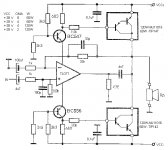
You probably want something more like Project 76: Opamp Based Power Amp - you can omit the first opamp stage if you want. Note that you will only be able to run +/- 15V supplies at the most. The diodes must be on the heatsink.
I have posted that circuit , and many told me it's not a " good " design .. tho it can output more power than op amp rails.
The 680 ohm resistors turn on the TIP's and the amp would work in class B ( if i remeber correctly . Here's the post.
http://www.diyaudio.com/forums/solid-state/304511-another-op-amp-based-amp.html
The 680 ohm resistors turn on the TIP's and the amp would work in class B ( if i remeber correctly . Here's the post.
http://www.diyaudio.com/forums/solid-state/304511-another-op-amp-based-amp.html
" Circuits like this run on a knife edge. The voltage developed across the 680 ohms determines if the output transistors turn on or not, and that voltage depends on the current drawn by the IC.
It is not a good circuit for an audio amplifier imo. You would need to tweak the resistor values to suit your transistors and opamp and even then, it would mean running in essentially class B. " - Mooly
It is not a good circuit for an audio amplifier imo. You would need to tweak the resistor values to suit your transistors and opamp and even then, it would mean running in essentially class B. " - Mooly
Yep.. well... pretty much any simple design like this is going to work like this. A headphone amplifier that only outputs a watt into 32 ohms is one thing... driving an 8 ohm load is another.
To be honest, if you want a power amp with a small amount of output power and a minimal parts count, build an LM1875 based circuit.
To be honest, if you want a power amp with a small amount of output power and a minimal parts count, build an LM1875 based circuit.
- Status
- Not open for further replies.
- Home
- Amplifiers
- Solid State
- Need some help :D