Both pre amplifiers and phase splitting channels are now adjusted and happily amplifying. I'm doing some measuring before rebuilding the output stages and was wondering how a (for example 20khz) square wave should look at the output of the phase splitter or pentode ? (No NFB)
Mine is not pretty 🙂 Sine wave is no problem.
Mine is not pretty 🙂 Sine wave is no problem.
Well there will be some slew rate limiting. I don't see a separate dominate pole in your design. How much smaller is 20KHz than 1KHz sine wave? In the LTspice simulation it maybe that the triode model has been used for U1. The screen resistor as a very rough rule of thumb is about 3x plate resistor for U1 so 560k.
Last edited:
Depanatoru I have implemented your suggestion an good progress here, Thx!
The open loop gain is now 194 (175mV RMS in , 34VRMS out. ) 0.5Vpp in / 96Vpp out.
So this seems to do the trick 🙂 😀 The DC values are a bit off compared to your set-up. The 6U8 pentode anode is 98.6V instead of 89 and the g2 is 53V instead of 99V and the cathode is at 1.9 V . Is this comparable gain as per your set-up ? Do I need to address the voltage differences ?
6U8 is ECF82 , so it is a different tube . Your setup could be good enough but for "perfection" you should lower the anode voltage to 80-90V to squeeze more max output from cathodyne at 350V . Maximum output swing , even if you don't need it for driving the output tubes , means lower distorsions at a lower level .
The 20KHz square wave is not important for audio , as is not desirable/possible to have too much bandwidth anyway .
Last edited:
Going for perfection. will lower voltage an the anode, is there a rule of thumb for the voltage on the G2 pentode ? (or how to calculate)
Thanks for the help guys.
Thanks for the help guys.
Valves vary enough that calculations can only get you in the ballpark. Although, each valve type could to massaged into a likely pair of series and shunt-to-ground resistors that would be most accommodating. It's been a while since I looked, but RDH4 discussed this. My memory is that using only a series resistor is not optimum, and you need both.
YOS,
Chris
YOS,
Chris
Ok adjusted the Anode resistor from 220K to 242K (added 22K) voltages are now in range.
Is it normal that there is ~7% difference between the tubes ? Anode voltage 87.1v L and 81.8v R channel. G2 @ Pentode 63v L / 51v R I use all 1% resistors and regulated 350V supply
Is it normal that there is ~7% difference between the tubes ? Anode voltage 87.1v L and 81.8v R channel. G2 @ Pentode 63v L / 51v R I use all 1% resistors and regulated 350V supply
Max headroom improved with compared to yesterday, 120V pp visually on scope, before clipping) moving on to the output stages
Thx Depanatoru and all others.
Thx Depanatoru and all others.
Yes 7% is normal. I would have altered the g2 resistor for the correct plate voltage but that's just my preference.
Think it is lost in the noise. As long as you have enough plate voltage to get into the 'saturation region' all will be fine. I think that's where a higher g2 voltage will help but somebody correct me if wrong.
Assuming a given (DC) anode load and a given cathode resistor, if you really, really need a certain anode voltage for any random valve of the type, you could make the G2 voltage adjustable, over some small range. If you can accept some tolerance of anode voltage, you may be able to design a voltage divider feeding the G2 to give you an anode voltage within your tolerance for valves within your tolerance. But, there is no magic design that will work with all *real* valves to zero tolerance.
YOS,
Chris
YOS,
Chris
And if I want perfect ? Better to change g2 resistor or doesn't really matter ? (for THD)
I didn't studied this too much , didn't saw anything important ... anyway if you change the G2 resistor/voltage you must change the rest of resistors for the same anode voltage . If you have plenty of time and some pots you can do it 😀
Some variation between tubes is normal , that's why we use matched pairs .
IvesH, I don't think the global feedback level has yet been defined in the thread - is that known or measured?
Do you know the stability margins at LF and HF ends with the default level of feedback, and resistive load, and were the margins changed by the PI input bias change?
Do you know the stability margins at LF and HF ends with the default level of feedback, and resistive load, and were the margins changed by the PI input bias change?
A final thank you
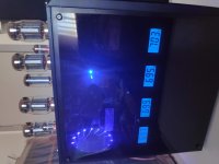
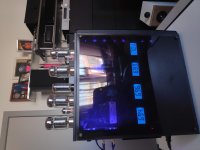
This baby is ready, KT88s are now driven correctly. The 6UA now works perfect with lots of gain and output voltage on the phase splitter.
28Watt RMS output / channel before clipping.
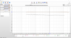
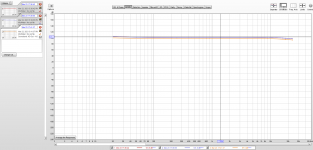
While I was at it I reconverted to UL and added a fixed -V BIAS for output tubes instead of cathode based bias. Biased at 70 mA but adjustable. I decided to regulate the NFB to 3 dB (also adjustable). I could get the frequency curve fully flat with more NFB but then it had the tendency to oscillate. THD measured at normal listen levels and. Left and Right channel are perfectly balanced in amplitude.
Thank you all for your input and helping my learning curve.
This baby is ready, KT88s are now driven correctly. The 6UA now works perfect with lots of gain and output voltage on the phase splitter.
28Watt RMS output / channel before clipping.
While I was at it I reconverted to UL and added a fixed -V BIAS for output tubes instead of cathode based bias. Biased at 70 mA but adjustable. I decided to regulate the NFB to 3 dB (also adjustable). I could get the frequency curve fully flat with more NFB but then it had the tendency to oscillate. THD measured at normal listen levels and. Left and Right channel are perfectly balanced in amplitude.
Thank you all for your input and helping my learning curve.
Attachments

Last edited:
If you want to increase the amount of NFB you may need to introduce a dominant pole into the design probably series R C across R2. Try sweeping up to 100KHz if you can.
Hi baudouin0 do you have an example diagram from an amplifier or own experience ? R2 you mean the plate resistor of the pentode ? in the original diagram ? (R4 in Depanatoru diagram) At present that is 242K , I'm googling schematics now 🙂
Yep plate resistor if I've got you diagram right. So try something like 22k+68p across this resistor say to get a pole of around 10KHz.
Ives, you really should plot the gain and phase without feedback first. Adding any supplementary phase/gain shifting circuits is best done with a knowledge of what they will do, and where to focus their effect to best improve closed loop gain/phase margins.
Your plots also indicate you can only measure from 20Hz to 24kHz - that is very limited when it comes to assessing LF and HF stability margins and performance. Is that really your limit range (as REW can compensate for drop off of an interface device, and has the ability to measure down to 2Hz, and generate signal to 1Hz)? Do you have any other test equipment? How did you know that the amp was oscillating when NFB was increased?
Your plots also indicate you can only measure from 20Hz to 24kHz - that is very limited when it comes to assessing LF and HF stability margins and performance. Is that really your limit range (as REW can compensate for drop off of an interface device, and has the ability to measure down to 2Hz, and generate signal to 1Hz)? Do you have any other test equipment? How did you know that the amp was oscillating when NFB was increased?
Last edited:
- Home
- Amplifiers
- Tubes / Valves
- Need some education - Negative feedback - Too much ?