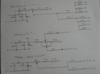
Need help on modding the bias circuit on my Mono block amps. Attached is three different circuits used to bias the output tubes. These circuits have been used on many version of this amp, and are on the many different schematics of this amp. I haven't seen version 1 on an actual amp, and don't know how it would works, but have seen the other two on working amps.
I now have some well used Flying C EL34's that have started to drift apart, say 24 to 38ma, and have a complete set of Mullard's to try. Since I have only one bias adjustment for each amp, mis matched tubes are becoming a problem as the original matched octets have drifted. The Flying C/Mullards test very good on my tester, so I would like to continue using them. I could go with Version 2 without a great deal of trouble. Is it the best option? A circuit board holds the tube sockets and the bias control connects at two separate locations, one for each set of four. Then traces carry this control to the 100 ohm grid resistors.
How could individual tube bias controls be implemented? Could the grid resistor be replaced with Bourns 3299 pots? Could someone give a circuit with these pots in mind that would allow individual bias control? Any better Ideas?
Attachments
more info
The chassis has limited interior space. Do you mean separate 5k pot, 100k resistor to each grid resistor? I would like to make the adjustment mechanics on the circuit board. What is it exactly how you would do this.
The chassis has limited interior space. Do you mean separate 5k pot, 100k resistor to each grid resistor? I would like to make the adjustment mechanics on the circuit board. What is it exactly how you would do this.
Agree with DF96.
Just put the pot at the earthy end of the bias chain with the wiper connected to ground so that if the wiper is intermittent, it will put FULL negative Bias on the Grid not ZERO bias as in your three circuits above. That way, your O/P tubes are protected against overload.
Just put the pot at the earthy end of the bias chain with the wiper connected to ground so that if the wiper is intermittent, it will put FULL negative Bias on the Grid not ZERO bias as in your three circuits above. That way, your O/P tubes are protected against overload.
The circuits 2 & 3 are crazy! One gives a bias voltage of -12.75 to -19V and the other gives -26.4 to -36V!
You must have some idea of the bias voltage requirement first, then you can calculate the required components around the 4 off 5k pots you intend to use.
These in parallel will equate to 1.25k so with the string as in circuit 2 you would have to increase the string current by at least a factor of 4. To get a swing of say -10 to -25V, the 6k8 will have to be lowered to 910 Ohms and the 5k1 lowered to 820 Ohms to get the same swing on each pot. This will require at least an extra 10mA approximately from the bias supply. You can reduce the string current by using 10k pots (6k8 now 1k8 and 5k1 now 1k65 (two 3k3 in parallel)) and this will set the string current at approximately 6mA. I agree that there is always the chance that a pot going open circuit could cause loss of bias but likewise, inserting a pot with its wiper at ground potential could also do this if set incorrectly. The circuit would effectively be a shunt circuit but to make it safe, the circuitry will have to be carefully planned such that the minimum position of the pot still maintains a reasonable voltage to bias back the tubes. My example values were worked on the basis that you intend to put all four pots, in parallel, into a single resistor string. If room allows, it probably would be better to make four individual strings and recalculate the string values required if necessary.
But first - decide on what voltage swing you need on each bias pot and then you can start from there.
Last edited:
- Status
- Not open for further replies.