Hi!
I had some spare parts of previous amp-projects and I decided to build my first "self designed" amp with them... what else... 🙂
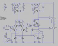
OK, its nothing special. I designed it basically as described in Slones book and added some nice things I found in this forum (thanks to everybody I have taken ideas from at this place). Schematic is attached below (hopefully). Its not finished yet... the output stage is currently missing, some parts have to be replaced by real-world cuircits, and some fine tuning probably has to be done.
Under normal conditions it simulates quite fine, so I decided to test some extreme situations like clipping. That's where bad things start: When driven into negative clipping (I wanted to have a look at this first, thats because the voltage of the VAS-transistor cascode is so high) it sticks to V- and stays there forever. It looks as Q7 and Q11 are saturating (and therefore Q11 draws a large current through its base - I guess Q11 wouldn't survive this in real world). In Slones "cookbook examples" I have seen a transistor to shunt away the base current of Q7. I tried this and it sort of worked... but output stays at V- for nearly the remaining negative cycle (at 1kHz) of the input before it reverts to normal behaviour - I am not really satisfied with this behaviour. I tried some other things (resistor in the collector of Q7, placing baker clamps...) but I didn't get results that satisfied me - although I must admit that some things I tried might not have been done correctly. I also changed the transistor types (to the MJE340/50) and with that models things looked better... so I don't exactly know at the moment, if my simulation only fools me (I have seen very similar schematics and they had apparently nothing special to prevent the behaviour I get... so it might be no problem at all).
I would appreciate any hints for solving this (if it has to be cared about at all) and other comments of course, too.
Thanks, stegmaie
I had some spare parts of previous amp-projects and I decided to build my first "self designed" amp with them... what else... 🙂
OK, its nothing special. I designed it basically as described in Slones book and added some nice things I found in this forum (thanks to everybody I have taken ideas from at this place). Schematic is attached below (hopefully). Its not finished yet... the output stage is currently missing, some parts have to be replaced by real-world cuircits, and some fine tuning probably has to be done.
Under normal conditions it simulates quite fine, so I decided to test some extreme situations like clipping. That's where bad things start: When driven into negative clipping (I wanted to have a look at this first, thats because the voltage of the VAS-transistor cascode is so high) it sticks to V- and stays there forever. It looks as Q7 and Q11 are saturating (and therefore Q11 draws a large current through its base - I guess Q11 wouldn't survive this in real world). In Slones "cookbook examples" I have seen a transistor to shunt away the base current of Q7. I tried this and it sort of worked... but output stays at V- for nearly the remaining negative cycle (at 1kHz) of the input before it reverts to normal behaviour - I am not really satisfied with this behaviour. I tried some other things (resistor in the collector of Q7, placing baker clamps...) but I didn't get results that satisfied me - although I must admit that some things I tried might not have been done correctly. I also changed the transistor types (to the MJE340/50) and with that models things looked better... so I don't exactly know at the moment, if my simulation only fools me (I have seen very similar schematics and they had apparently nothing special to prevent the behaviour I get... so it might be no problem at all).
I would appreciate any hints for solving this (if it has to be cared about at all) and other comments of course, too.
Thanks, stegmaie
Attachments
Obvious problems:
Output emitter R values
“Vbe multiplier”
transistor models/type selection: I haven’t looked for the problems in your models but selecting from SwCad’s supplied models improved things for me with your circuit
generally you’ve started at the wrong end of the amp to "improve" the circuit, the output stage has insufficient current gain if you intend to drive a typical speaker and the lack of current gain means the major nonlinearity is the output device base current loading the VAS
cascodes are cool looking but don’t improve my sims until the basic topology gets to better than –100 dB distortion figures, output stage loading effects with at least nominal speaker load should be addressed first
That's what I encountered, too... and that's why I'm not sure if there's a general problem or if it is only in the simulation due to some bad models (which are mostly from the manufacturers sites)jcx said:transistor models/type selection: I haven’t looked for the problems in your models but selecting from SwCad’s supplied models improved things for me with your circuit
As I said at the beginning, the output stage is not yet finished. The two MJE will be only the drivers for two pairs of 2SA1216/2SC2922... I did not include them, because I wanted to have some things sorted out before...generally you’ve started at the wrong end of the amp to "improve" the circuit, the output stage has insufficient current gain if you intend to drive a typical speaker and the lack of current gain means the major nonlinearity is the output device base current loading the VAS
They are necessary e.g. for the MAT. I played around a bit with the others (another reason for designing this one is that I want to learn how things work and not only build available kits as I have done before)... and I will probably remove some and replace the corresponding transistors with higher-voltage types (that's what I meant with fine tuning, I have also seen that they don't change much).cascodes are cool looking but don’t improve my sims until the basic topology gets to better than –100 dB distortion figures, output stage loading effects with at least nominal speaker load should be addressed first
Thanks,
stegmaie
Hi stegmaie,
Some random remarks - as I didn't look that much into the concrete circuit, they may partially not apply.
- Fairchild KSA models:
These are LEVEL 2 models, whatever this may imply. I've found that some characteristic curve plots from them look very reasonable. But there may be a problem when the models are driven to unusual states. Or perhaps LTSpice has some bug left in LEVEL 2 handling, which went undetected so far, as these models are rarely used.
Better head over to http://groups.yahoo.com/group/LTspice/ to ask!
- amplifier modelling
Try to look at the amp without NFB applied, I find this rather instructive and worth the fine tuning to find the right operating point.
If you have so much NFB, that it's impossible to set a working point for this mode, the simulation with NFB applied is of doubtfull worth, IMHO.
- driving VCE smaller than VBE
Perhaps insights can be found in this thread (usage of Baker clamp)
http://www.diyaudio.com/forums/showthread.php?postid=299168#post299168
Regards,
Peter Jacobi
- Status
- Not open for further replies.