Fully agree with above written excellent advice and add a bit on how to read that datasheet.
Which doesn´t actually *lie*, everything it says is truth, but please consider all warnings, caveats, "buyer beware" and "YMMV" type stuff :
Datasheet:
https://www.st.com/resource/en/datasheet/cd00001887.pdf
1) Prominently displayed on header:
2) just 2 lines below that, in slightly smaller letter size:
Hey!!!! what happened to "120V" ????
3) another 2 lines below that:
a) 100W @ 10% distortion which is a quite clipped signal amounts to about 80W unclipped ... so no "real" 100W to begin with.
b) And the first time they speak about it putting out some power, they again downgrade voltage rails to +/-40V , go figure.
4) and later,once you do the Math on output current capabilities, which are limited for safety,you will downgrade real output power even more.
Besides, plain limiting by hitting rails, which will happen somewhat earlier if you lower rail voltage, does not sound as bad as clipping created by foldback current limiting/short circuit protection built into this amplifier.
They look about the same when driving purely resistive loads, but when driving highly reactive loudspeakers they "trigger early" and produce horrible buzzing sound.
So in the real world, using the apparently "reduced" rail voltages suggested above (+/-32V) will actually provide the maximum available power, if you want it to be clean and driving real World speakers.
5) besides datasheets, lookat it from another side:
* same case size LM3886 is rated 50/60W RMS into 8/4 ohm loads, is famous for its reliability and high quality sound and is still very popular, even if it´s quite older, while TDA729x, which "should" have replaced it in full, actually did not, got a reputation of unreliability, backed by user experience, so much so that a few established MI amplifier manufacturers have been "burnt" by trusting its promise:
Fishman used it as a 100W power amp in one of its Loudbox Acoustic Guitar amplifiers: it fails often.
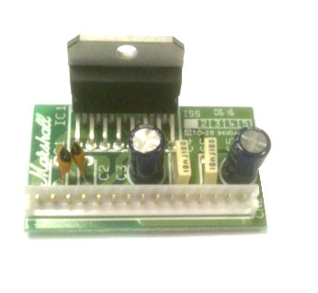
Marshall used it a lot, from 100W MG Guitar amps to MF350 350W RMS monsters, using 4 of them in bridged parallel configuration: they fail so much that they had to offer a user-replaceable plug in (no soldering involved) miniboard so they could be "repaired at home", go figure:
In a nutshell: that small case, exactly the same as 2 x TO220 cases side by side, can safely dissipate heat produced by a 50/60W amplifier, experience has shown it is not enough for 80/100W ones, so it´s prudent to use it within safe limits.
Yes, you probably *can* pull 100W from one of them ... for a short time and if you are not terribly worried about distortion and reliability, but ... why bother?
Want more power out of a "chipamp"?
Have a look at Sanken or Sanyo STK modules ... only problem is that they are much larger, more expensive ... and not *really* chipamps but hybrid modules, which can be described as a "Factory packaged ... discrete amplifiers .... "
See it by yourself:

they even have not-so-tiny PCBs inside 😱
That was an eye opener for data sheets with their big values for marketing. If they would only put a practically usable rating at the beginning it would save a lot of time and effort, at least for first timers like myself. Thank you.
Yeah I will keep that in my mind from now on lol.Be very careful with spec max volts for chip amps as I have seen it specified at a high voltage but with the input shorted !!!!!
A bit stupid spec-ing for the input shorted when you want it to function as a power amp.
I wont run my 7294's off anything over +/- 35 volts DC.
22x√2 is the theoretical value. But, that is with nominal current loading and without taking rectification into account. This corresponds to 31Vpeak with nominal load. Then, no account has been taken of rectification, winding resistance and leakage inductance when estimating the idle voltage. My experience is, you end up with an idle DC voltage close to 1.5 times the nominal AC voltage. This should be close to 33V. When you start loading the 33V, it will drop somewhat.
22x√2 is the theoretical value. But, that is with nominal current loading and without taking rectification into account. This corresponds to 31Vpeak with nominal load. Then, no account has been taken of rectification, winding resistance and leakage inductance when estimating the idle voltage. My experience is, you end up with an idle DC voltage close to 1.5 times the nominal AC voltage. This should be close to 33V. When you start loading the 33V, it will drop somewhat.
I see. In theory I am limited by the current limiter 6.5A. I happen to have a 24 v transformer. Using 6 ohm speaker I will stay below that. Do you think it will be ok overall to use this transformer?
You say a 24V transformer. 1x24Vac or 2x24Vac? What power rating (VA)?
It's 2x24VAC and outputs max 6A current
In such case I would use that 2x24V (300VA) transformer. The rectified idle voltage will be around 36V. With a 6 Ohm load, the current limiter will not be invoked. In 6 ohm, you will have around 85W!
You may even use 4 Ohm speakers for playing at low volume. At high volume you risk invoking the current limiter and that is not going to sound pretty as explained by Mr. Fahey. The heating is also going to increase with lower speaker impedance.
Now you save money on the transformer, spend a little on a good rectifier decoupling board with 6800uF-10000uF decoupling per rail and per amplifier board. Mooly identified this deficiency with the present reservor capacitors. You do not need to buy very expensive capacitors with the lowest ERS, Nichicon or Rubycon capcitors will according to my experience do. Running a good amplifier from a good transformer but with poor or insufficient reservoir capacitors will spoil the pleasure. Mooly's advice to get a separate rectifier/capacitor board and short-out the rectifiers on the amplifier boards is really good.
And, as DPH explains, the IC will get hot when you play loud. Use a good size heatsink (with proper insulation to the chips!), eventually one you have salvaged from a scrapped amplifier. When the heatsink gets so hot that it is unpleasant for you to touch, imagine how the ICs feel.
Both for you and other who may read this, as expressed by Mr. Fahey, start teaching yourself to understand a datasheet. You cannot rely on values stated by Internet sellers simply because many of them are traders and do not know. They are told something (exaggerated) by a supplier. Even datasheets exaggerate sometimes by giving impressive values but under unrealistic conditions. Only by understanding how to see through the characteristics listed in the datasheet, you get close to the truth.
Good luck with the project.
Last edited:
In such case I would use that 2x24V (300VA) transformer. The rectified idle voltage will be around 36V. With a 6 Ohm load, the current limiter will not be invoked. In 6 ohm, you will have around 85W!
You may even use 4 Ohm speakers for playing at low volume. At high volume you risk invoking the current limiter and that is not going to sound pretty as explained by Mr. Fahey. The heating is also going to increase with lower speaker impedance.
Now you save money on the transformer, spend a little on a good rectifier decoupling board with 6800uF-10000uF decoupling per rail and per amplifier board. Mooly identified this deficiency with the present reservor capacitors. You do not need to buy very expensive capacitors with the lowest ERS, Nichicon or Rubycon capcitors will according to my experience do. Running a good amplifier from a good transformer but with poor or insufficient reservoir capacitors will spoil the pleasure. Mooly's advice to get a separate rectifier/capacitor board and short-out the rectifiers on the amplifier boards is really good.
And, as DPH explains, the IC will get hot when you play loud. Use a good size heatsink (with proper insulation to the chips!), eventually one you have salvaged from a scrapped amplifier. When the heatsink gets so hot that it is unpleasant for you to touch, imagine how the ICs feel.
Both for you and other who may read this, as expressed by Mr. Fahey, start teaching yourself to understand a datasheet. You cannot rely on values stated by Internet sellers simply because many of them are traders and do not know. They are told something (exaggerated) by a supplier. Even datasheets exaggerate sometimes by giving impressive values but under unrealistic conditions. Only by understanding how to see through the characteristics listed in the datasheet, you get close to the truth.
Good luck with the project.
Thank you very much for all the guidance 🙂
Hello. I would like to know can I power 4 mono boards tda7293 with only 1 transformer which has output 45-0-45 vac ? Transformer is taken out from some sony amplifier which has stk4221 chip inside.
Of course I'm considering to put proper heatsinks on all boards and if I need to I will put some fan and I don't expect more than around 50w clean power per board.
Thanks for any help.
Of course I'm considering to put proper heatsinks on all boards and if I need to I will put some fan and I don't expect more than around 50w clean power per board.
Thanks for any help.
> 45-0-45 vac ... around 50w clean power per board.
45-0-45VAC works out to like 200 Watts in 8 Ohms, doesn't it?
45VAC * 1.414 = 63VDC
Assume 10% losses in amplifier. Say 56V peak, 40V rms. Looks like 200 Watts here.
45-0-45VAC works out to like 200 Watts in 8 Ohms, doesn't it?
45VAC * 1.414 = 63VDC
Assume 10% losses in amplifier. Say 56V peak, 40V rms. Looks like 200 Watts here.
It doesn't have to be 50w, it doesn't matter how much watts is gonna output, 50w was just some average number cuz I don't expect from chinese board to get hundreds of watts even with proper supply.
Transformer was been in Sony mhc-rx99 with stk4221 chip which has rating 240w on 8-16 Ohms and I guess than transformer should be probably around 300w (size is like transformer from microwave oven).
I'm planing to use boards with 8 Ohm speakers, if it would be better I can make them even more than 8 Ohms. I'm going to build boxes with speakers and I can mess around with adding speakers and changing resistance.
> Sony mhc-rx99
OK, one of those.
The actual delivered DC Volts was +/-48V at idle. This obviously sagged a LOT at full roar because the box was rated 80 Watts @8r clean or 35V peak. The "Music power 170+170" rating suggests 51V peak which is more than the idle power rail so is surely pretty clipped.
The power supply makes 48+48= 96V and the TDA7293 is rated 120V. It can work (but see JMFahey's remarks above). It will not tolerate careless or sloppy craftsmanship. Hmmm... the TDA7293 sells for $13 which is a lot less than I used to pay for blowing-up all the outputs of my 27 Watt amp.
And of course with the same power transformer the power output will be very nearly the same as when it was a Sony: 80W clean 100W blasting, which is serious power for the home, especially in serious speakers.
EDIT: ah, you want _four_ channels? Try it. It will certainly play medium loud. Sneak up the volume and keep feeling the power transformer (be sure all joints are perfectly insulated!!). The RX-99 was designed just-good-enough for two big stereo channels. Four channels pushed hard may shorten its life.
Last edited:
Thanks for explaining. 🙂 That's all I need, only to be sure aren't they gonna blow up on my current transformer.
I bought 4 boards for 22$, that's cheap but I really don't wanna wait for months, specially in these hard times, for boards to arrive and than to blow them off cuz of mine stupidity.
Exactly, for 1 room 50w with nice speakers is more than enough power. I wanna make it for myself, not to disturb all around neighbours with my speakers. 😛
Yeah I was bought 4 boards to have for channels but it doesn't have to be 4 channels. I would be satisfied with just 2 channels if that way I would get cleaner and better power from only 2 boards?
Other 2 boards was bought cuz they were all cheap and I thought if I connect 4 of them on that transformer than I will get less chance to blow them up, at the end boards are chinese and I can't be sure are chips real or some fake but transformer is very real 😀
Ps. Thanks a lot again for all explanation, I'm almost noob for most of these kinda things but I'm enjoying in diying them and every help and advice are very welcoming. 🙂
Little update 😀 . Boards are came today and I was testing pins 5, 10, 11 like I found how to test chip if it's fake and on all boards on those chips I'm getting same reading on all chips (around 5 or 6 Mohm on some cheap Chinese multimeter) and writing on chip isn't some of those bright ones, so I guess I'm lucky and got real thing or there is some other catch to fake them ? ��
Sorry but , are you man serious !!!
you want to find fakes ( mostly from China ) with cheap Chinese meter 🙄
making audio gears is not a matter of "luck" , well , for some serious guys , in some occasion , it might be , but it isn't your case , at all ....
.
you want to find fakes ( mostly from China ) with cheap Chinese meter 🙄
making audio gears is not a matter of "luck" , well , for some serious guys , in some occasion , it might be , but it isn't your case , at all ....
.
Last edited:
Of course I'm serious. 🙂
I'm sure multimeter if it's cheap and chinese didn't made strictly to fake results on audio chips, it could be less precise comparing to some expensive and better quality ones but still can do good enough job for diy person.
I don't think diy person isn't some of those serious guys and this is a diyaudio forum. Almost everything from china is gambling and sometimes is good luck with quality and sometimes is wasting of time and little money cuz it's usually cheap. So for sure if I have money or want to buy some expensive and original amplifier or any of those high end audio gears than for sure I wouldn't diying nothing around that cuz obviously for that price and quality people working whole life on improving it and making it better, I'm not on that level, but there is a china where I can find some cheap products and try to make something decent and I won't be sad or disappointed if I don't get some high end quality from it. At the end I'm enjoying in diying and I'm happy when I make it good from something cheap and trashy. 😀
- Home
- Amplifiers
- Power Supplies
- Need solution for powering two TDA 7293 boards