HI !
My new preamp have balanced output 7.1 and I need to build new gainclone with BALANCED INPUT.
If anybody can help me with BALANCED INPUT shematic diagram to build mono LM4780 I appreciated that 😉 !
thanks in advance 😀
nicK
My new preamp have balanced output 7.1 and I need to build new gainclone with BALANCED INPUT.
If anybody can help me with BALANCED INPUT shematic diagram to build mono LM4780 I appreciated that 😉 !
thanks in advance 😀
nicK
Use an IC like INA134 as the balanced input. The datasheet on BB site has the diagrams.
However, u will have to derive or construct another psupply to suit these ICs.
You can also make balanced input circuit using an audio quality opamp. The simplest of these may be NE5532.
Edit: On second thought, u only need audio buffers on each line (+ and -) of the balanced signal to drive 4780 in bridge mode. A gain stage also may be needed if the signal level is low.
If u follow this path, you should not construct the bridged application of LM4780. Instead construct a stereo application as the two input signals are already differential.
Gajanan Phadte
Last edited:
thanks for your answer ! 🙂
I search to have minimal signal treatment (old school audiophile)
I find guy how entrer signal IN - and IN + on each side of the LM4780 to output in mono. picture: Audiosector Lm4780 balanced amp project - pink fish media
but I don't understand how it can work if one signal is inverted of 180 degree ?
thanks in advance to help me to understand 😉
nicK
My solution was minimal, as u say. But connecting a power amp chip directly to the balanced drive may not sound that good. Moreover, the 4780 is not designed to have long cables connected to its input. I suspect that link assy has this problem.
In fact, as I explained, that circuit in the link is a stereo application and not the bridge application. The bridge application, if u see properly, needs 180degrees signal on the other channel.
Gajanan Phadte
In fact, as I explained, that circuit in the link is a stereo application and not the bridge application. The bridge application, if u see properly, needs 180degrees signal on the other channel.
Gajanan Phadte
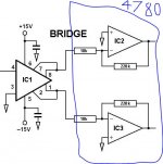
Here is a diagram I found on the net. Consider IC1 as your preamp. IC2 and IC3 are now the two channels in the 4780.
Gajanan Phadte
The diagram is for illustration only.
Gajanan Phadte
The diagram is for illustration only.
Attachments
Last edited:
You don't need to build a new gainclone and you can hang onto it as a stereo amp. You just need to connect it differentially, so that the + goes to the positive input and the - to the inverting input. You will just need a couple more resistors so you have the same input impedance on each side. It is a very standard topology and is used all over the place but needs to be understood in the context of the 3886.
The topology can be seen here on the RHS of Fig 2.1.
http://www.jensen-transformers.com/an/an003.pdf
Note that the resistor at In+ goes to ground and the other f/b resistor is just as it was. Matching the resistors will incidentally bring benefits. Ignore any capacitors in the diagrams for your purposes.) So it's really just the same topology as you are used to, but now on both inputs
Do this for both channels on the 4860. And reading the rest of the paper is almost certainly worthwhile.
- Status
- Not open for further replies.
- Home
- Amplifiers
- Chip Amps
- need shematic for BALANCED INPUT LM4780