Member
Joined 2009
Paid Member
Hi, I'm about to cut into the front baffle but the drawings on the downloadable pdf for the Alpair 10.3 are nearly useless - they are so small and fuzzy I can't read the data from them. Anybody have proper and reliable dimensions for the cut outs needed for this driver (with bezel) into 17.5mm birch plywood ?
As Jeff says, you could just zoom in on the PDF drawing, but short answer is with bezel:
OD = 165mm
ID = 139mm
rebate depth ( Z)= 11.8 ( test to allow for minor compression of molded gasket)
without bezel:
OD = 160mm
ID = 139mm
rebate depth = 10.5mm
If you're planning on CNC routing of the rebates, I'd suggest allowing at least and extra .5mm dia on both through hole and recess for ease of installation / removal of drivers - if they're too tight and you need to force them to fit, you're asking for trouble - and of course if you ever need to remove the driver
Member
Joined 2009
Paid Member
Member
Joined 2009
Paid Member
The original drawing(s) imbedded ino the MA pdfs are here. Except for the addition of the optional bezel cover & super gaske with the A10.2 baskets are the same across all 10s
Frugal-phile | Box Library / Mark Audio
dave
Frugal-phile | Box Library / Mark Audio
dave
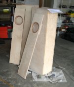
I've just finished milling the panels for the A12.2P Pencil from 3/4" Baltic Birch ply and am backing the inside of the front baffle with a square of 1/2" ply so that the screws can bite into approx 3/4 inches after rebate....
don't forget to chamfer the rear side before assembly!
Member
Joined 2009
Paid Member
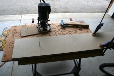
I had a bash at some routing. It's been a year since I built the Big'un speaker and as a result it took hours to locate the relevant tools 
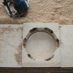
Still, I managed to find it all. First image you see the set-up, with a drill bit sticking out as the centre-pin which pokes through a strategically placed hole in the scrap wood screwed to the base of my router to ensure the right diameter circle. I erred on the generous size for the outer circle to get a diameter of order 168mm and a rebate depth of a hair over 12mm. The inner circle, the cut-out, is something of worry because if you make this generous there's a risk of not leaving enough land for the mounting screws. The Alpair drivers have very little tolerance in this regard. I opted to under-size slightly at around 134mm diameter. I'll then manually enlarge the cut-out to suit the plastic frame supports. My router doesn't go through the total baffle thickness so I had to turn the pieces over and route from the back to complete the cut-out. To get the front and back cut-outs to line up you need to drill a perpendicular hole in the centre for the centre-pin. I managed to do a good job of this on one baffle, but the other was out (I really do need a drill press).
And the chamfers at the backside are done too.
Attachments
Member
Joined 2009
Paid Member
Has anybody figured out how to do the scallops without setting fire to the baffle?
It's a sign of serious DIY
I do like the two-stage chamfer. I might try that.
It wasn't the intent when I started
CNC router and very careful alignment ?Has anybody figured out how to do the scallops without setting fire to the baffle?
when I care enough about it, I'll just tidy up with some 80G PSA sandpaper wrapped on a scrap of 1 1/4" closet rod
I think that was accidental?I do like the two-stage chamfer. I might try that.
Bob
Frankly i prefer a gouge, rasp and a few linesHas anybody figured out how to do the scallops without setting fire to the baffle?
I do like the two-stage chamfer. I might try that.
Bob
Frankly i prefer a gouge, rasp and a few lines
Do you do a few lines before or after you work on your speakers?
Bob
Do you do a few lines before or after you work on your speakers?
Bob
Sorry i ment to say a gouge,rasp then a few line
Member
Joined 2009
Paid Member
Member
Joined 2009
Paid Member
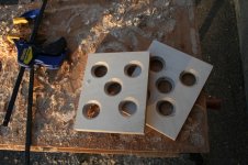
Some progress has been made on the porta-bench in my driveway
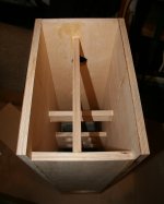
A couple of holey braces were positioned starting just below the driver cut-out where I want to stiffen things the most. Both braces are vertical, one front-to-back and the other side-to-side.
I then installed a number of other criss-cross braces from left over 2" wide 'sticks'. In particular I wanted to brace the port opening against the back of the box since the open edge is not supported otherwise.
I installed some thick felt lining around the inside of the top part of the box to tame high frequency reflections.
The driver has been dry-fitted to test the opening dimensions.
I'm probably about half way through the work effort now. It needs A LOT of tidying up before it looks presentable.
Attachments
- Status
- This old topic is closed. If you want to reopen this topic, contact a moderator using the "Report Post" button.
- Home
- Loudspeakers
- Full Range
- need quick help with A10.3 info !