TomWaits said:
Todd, send me an email, as I can't get through to yours.
Shawn.
But if for some reason it still doesn't work try:
100 amps at gmail dot com - minus the spaces, etc.
..Todd
taj: " ... Another option I'm considering is maybe to try the LM4702 in front of the Bryston's output section (4 pairs of TO-3 devices per channel at 72 volt rails). This way, I could try a new amp design without butchering the 4B completely beyond restoration. ..."
Back on track, using the Bryston 4B chassis 🙂
This sounds more interesting. What other parts might you change from National's original design reference?? ( re: http://www.national.com/images/pf/LM4702/20158319.pdf )
... or is it possible to simply use your P & N channel pairs coupled directly (replacing the Darlingtons. etc., paying attention to the feedback resistor(s) and Q/mult1, Qmult2, etc.) ??
Incidental: Is there room on the sinks to thermally "couple" the LM4702 to TO3 pairs? The '4702 does not thermally limit its on chip output section to the drivers except thermally. (This may not be as serious as I believe, but I still think it might be a good idea = it might be the only way to override possible P & N transistor thermal runaway, which with good layout and careful parts selection may not be a problem at all.)
Got schematic ?? Point to point from one of the DIY boards ?? ... or would you do your own board ??
taj said:The existing circuit boards (shown in green) are about 4.5" wide mounted vertically and they use 2 daughter output boards. The blue one is an I/O and power board. The existing power supply provides approx. +/-72V rails.
I was thinking maybe a Leach amp, with additional output devices, but I don't know enough about electronics to modify that circuit without serious help from this forum. But any other ideas are welcome.
In the site of Bryston there isn't schematic about your versione of 4B. But I suppose they are built with the same topology of other Bryston power amplifier, which is yet a substantial implementation of a Leach-style output amplifier with the only particularity, really a "bryston think", of output stage arrangement, which improve really the complementarity of output stage.
I dont' know the purpose of your retrofit but, if I was in your odds, I've thought for the maximum restoration of circuit instead of building a new one. That's because circuit, once it was seriously optimized (and Bryston is serious enough...), it's not so important for sound as other more *systematic* arrangements.
Howewer:
1) Having two amplifier to tweak, i would seriously plan to *bridge* each one in a mono amplifier with halved power supply (+/- 36 Volt, instead of +/- 72 as it's now).
2) Plan a *true differential* system from input to output, rearranging the power supplys in a fashion for which any "ground audio system" (signal and power) will be *totally* separated from any ground system of power supply (which, at most, interest just the chassis but not any signal path.
3) Any other items eventually involved with point (1) and (2) - The strategic ones for my idea of retrofitting these power amplifiers.
Hi
Piercarlo
Piercarlo: " ... 1) Having two amplifier to tweak, i would seriously plan to *bridge* each one in a mono amplifier with halved power supply (+/- 36 Volt, instead of +/- 72 as it's now). ..."
This might cover my own desire for balanced input(s) and a mono-block version !!
This might cover my own desire for balanced input(s) and a mono-block version !!
FastEddy said:This might cover my own desire for balanced input(s) and a mono-block version !!
When i get a bit of free time to put hands on illustrator; I'll draw a block schematic which may serve as a guideline for arranging an existing (good!) stereo power amplifier in order to "rebuild" it as a differential mono amplifier with minimal circuit retouching - mainly about input stage and signal ground general rereferencing to a different one from the supply ground plus some tipe about DC current speaker protection (mandatory for bridged amplifiers!).
The better amplifier topology for this arrangements are the full complementary from input to VAS.Output stage is less critical and may be, if no better things are available, also a classical quasi complementary output stage, because simmetry is guaranteed from bridging, not from the topology of single amplier stage.
The need of "full complementarity" of stages from input to vas is related with the goal of dereferencing signal grounding from any other system ground, which imply some rearrangements in general feedback and, last but not least, some "neutralization" of supply rails, which normally acts as "ancillary grounding" (with problems!) for AC signals.
Ciao
Piercarlo
balanced input front end
Piercarlo: " ... I'll draw a block schematic which may serve as a guideline for arranging an existing (good!) stereo power amplifier in order to "rebuild" it as a differential mono amplifier with minimal circuit retouching - mainly about input stage and signal ground general rereferencing to a different one from the supply ground ..."
Optimally, I would want a simpler change to the front end(s), basically just a balanced input for dual channel output(s), rather than a complete redesign of purpose of the LM4702.
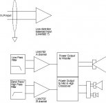
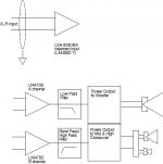
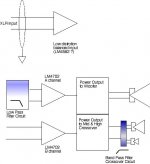
Eventually, I would want to use the LM4702 (or other) as a bi-amp speaker driver, bass woofer (without crossover) plus middie & tweeter (with simple band pass passive crossover), not necessarily for "boosted" power (ala bridging) but for remote speaker feed by XLR signal cable from the pre-amp ... The goal being to reduce or eliminate those large, costly, heavy chokes and capacitors of the low pass part of the crossover, replaced with "active" low pass and band pass filters in front of or following the LM4702, with the much smaller middie & tweeter band pass crossover further reduced in size, costs and weight ... and ... get the better quality balanced inputs.
Maybe all I would need is something a little like this: http://www.national.com/pf/LM/LM1036.html ... as a front end w/ gain control & "adjustable" low pass & band pass filters ... feeding the LM4702 as power amp front end ?
Your offer of sketches, block schematics and/or diagrams of a bridged output LM4702 will of course be appreciated, especially as I am sure we will learn a great deal more about "balancing" inputs ... of what would ultimately be a balanced input, mono-block using this superior chip.
😀
Piercarlo: " ... I'll draw a block schematic which may serve as a guideline for arranging an existing (good!) stereo power amplifier in order to "rebuild" it as a differential mono amplifier with minimal circuit retouching - mainly about input stage and signal ground general rereferencing to a different one from the supply ground ..."
Optimally, I would want a simpler change to the front end(s), basically just a balanced input for dual channel output(s), rather than a complete redesign of purpose of the LM4702.
Eventually, I would want to use the LM4702 (or other) as a bi-amp speaker driver, bass woofer (without crossover) plus middie & tweeter (with simple band pass passive crossover), not necessarily for "boosted" power (ala bridging) but for remote speaker feed by XLR signal cable from the pre-amp ... The goal being to reduce or eliminate those large, costly, heavy chokes and capacitors of the low pass part of the crossover, replaced with "active" low pass and band pass filters in front of or following the LM4702, with the much smaller middie & tweeter band pass crossover further reduced in size, costs and weight ... and ... get the better quality balanced inputs.
Maybe all I would need is something a little like this: http://www.national.com/pf/LM/LM1036.html ... as a front end w/ gain control & "adjustable" low pass & band pass filters ... feeding the LM4702 as power amp front end ?
Your offer of sketches, block schematics and/or diagrams of a bridged output LM4702 will of course be appreciated, especially as I am sure we will learn a great deal more about "balancing" inputs ... of what would ultimately be a balanced input, mono-block using this superior chip.
😀
Re: balanced input front end
Hmm... This might be acceptable for a subwoofer crossover, but IMHO using textbook filter circuits would not be utilizing the speakers to their best. Currently, configurable digital or custom passive crossover circuits (with a good modelling/measuring application) are the only efficient way to adjust the exact phase/slope/Q parameters needed to get your speakers sounding their best. That's not to say it's impossible, but certainly not easy.
...Todd
FastEddy said:Piercarlo:
The goal being to reduce or eliminate those large, costly, heavy chokes and capacitors of the low pass part of the crossover, replaced with "active" low pass and band pass filters in front of or following the LM4702, with the much smaller middie & tweeter band pass crossover further reduced in size, costs and weight ... and ... get the better quality balanced inputs.
😀
Hmm... This might be acceptable for a subwoofer crossover, but IMHO using textbook filter circuits would not be utilizing the speakers to their best. Currently, configurable digital or custom passive crossover circuits (with a good modelling/measuring application) are the only efficient way to adjust the exact phase/slope/Q parameters needed to get your speakers sounding their best. That's not to say it's impossible, but certainly not easy.
...Todd
taj: " ... This might be acceptable for a subwoofer crossover, but IMHO using textbook filter circuits would not be utilizing the speakers to their best. ..."
Exactly!! That's why the middie & tweeter have their own passive crossover (the woofer's crossover being an "active" low pass filter, ahead of the output drivers or ahead of the input).
taj: " ... the only efficient way to adjust the exact phase/slope/Q parameters needed to get your speakers sounding their best. ..."
I could put some kind of "parametric" EQ circuit in front of the input and eliminate all the extra parts in the above diagrams ... or simply fall back of those huge, heavy, costly chokes and caps needed to "properly" make the low pass woofer crossover ... 🙁
BUT I still need to have a balanced XLR input in order to satisfy my requirement.
(It is my experience that parametric active equalizers as buily into pre-amps are noisey and sensitive to dynamic audio (usually A to D and D to A circuits = avoided in quality and high end audiophile systems ... no?)
😕
Attachments
taj: " ... Would you two be able to help me create an amp based on the LM4702 and this output section ..." ( http://members.shaw.ca/toddj/files/output-section.pdf )
1) It would help if the parts had more labels: Q1, Q2, ... C1, C2, ... etc.
2) There appears to be more here than is needed ... but I'm sure not the expert ... VLSI and/or AndrewT and several others are going to have a better handle on this than I am.
😕
1) It would help if the parts had more labels: Q1, Q2, ... C1, C2, ... etc.
2) There appears to be more here than is needed ... but I'm sure not the expert ... VLSI and/or AndrewT and several others are going to have a better handle on this than I am.
😕
Okay, I added labels.
And yes, I have no idea what the circuitry before Q7-Q8 does. The rest is fairly obvious to me. This is one of the reasons I help with this.
..Todd
And yes, I have no idea what the circuitry before Q7-Q8 does. The rest is fairly obvious to me. This is one of the reasons I help with this.
..Todd
And for what it's worth, this is my own drawing and reverse engineering of a wonderful sounding amplifier we own at the sound company. It's about the same output power as a 4B and has reasonably similar rail voltages. Hence my interest.
..Todd
..Todd
I think it's a great idea to gut and replace the amp in the 4B. I'm getting excited about doing the same with a Technics SE-A5.
FastEddy said:taj: " ... This might be acceptable for a subwoofer crossover, but IMHO using textbook filter circuits would not be utilizing the speakers to their best. ..."
Exactly!! That's why the middie & tweeter have their own passive crossover (the woofer's crossover being an "active" low pass filter, ahead of the output drivers or ahead of the input).
Ok. However this is a completely different idea from mine. I've think to use bryston for a full range differential system, not for a semi-active crossoverd system (which remain essentially single ended). For differential to single-ended converter there are a lot of linear devices available from semiconductors firm. Is only a question of browsing their datasheet depots and finding some suitable IC for the purpose. Isn't nothing of "dramatic".
Hi!
Piercarlo
Hi taj
Wow I am no electronics engineer, I am just experimenting myself.
I have recently modified 2x LUXMAN 5L15 amplifiers by pulling out all the bits up to the driver transistors (also left in the VBE multiplier stage) and strapped in an LM4702.
The improvement is sound quality was very obvious to the owners and me.
The layout of this amp made it very easy to mod and it had a +/- 60v regulated PS I could use for the LM4702.
This is not necessary but increases output by aprox10% and can improve performance.
I have photos of the modifications if you are interested.
Mk-2 LM4702 Amplifier made in the wreck of a KODA A-260 (DSE A-2760)
The same parts list as the NS applications note, except for 0.22ohm emitter resistors (I had some thick film resistors to use)
300va transformer, DC protection PCB, RCA input switch PCB, Power switch PCB, 4x 10,000/50v caps are from the original KODA.
+/-45v with separate =/- 50v for the chip (Unregulated filtered with 2x 2,200uf)
Output is 2x 85w RMS 8ohm / 2x 135w RMS 4ohm
Sounds great, much the same as my Mk-1
DC coupled (although there is provision on the PCB for capacitors)
Home made SS PCB,s
The only parts I had to buy where the 4x output transistors AU $4.00ea + PCB the rest was recycled junk lying around my workshop.
Next I hope to make another the same but with Sanken SAPxxx transistors.
Attachments
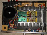
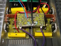
VLSI said:Another photo
VSLI, nice simple project! Thanks for the photos.
So, if I understand you correctly, the existing amp channel PCBs are not really being used, as you've tapped in at the driver transistor; and the LM4702 is on the PCB that's upside-down, physically mounted to the copper strap that spans the 2 heatsinks?
Did you also make the DC protection PCB? Is there any output short-circuit protection in this configuration?
...Todd
- Status
- Not open for further replies.
- Home
- Amplifiers
- Solid State
- Need project ideas to fit this chassis