I have seen a trick mentioned in sub design where the sealed box is deliberately made smaller than normal (Qc >> 0.7) and resulting sub driven entirely in the band below Fc with a 2nd order compensating filter. Unfortunately I can't find the information. Does anyone have a pointer to a discussion of this approach?
Quote from the web
An interesting variation on the sealed box is the Extended Low Frequency (ELF) design. (Note that "ELF" is a trademark of Bag End Loudspeakers, one of several companies supplying commercial subwoofers based on this design principle.) An ELF system is simply a sealed box which is operated only below the low frequency -3 dB point (F3). This has several advantages as well as several obvious disadvantages. The advantage include:
* Very small boxes are not only possible, but actually desirable since F3 becomes the upper limit rather than the lower limit of the passband.
* The impedance is quite constant and stable below F3. thus presenting an easier load for an amplifier.
Nothing's free, however, and ELF designs suffer corresponding disadvantages:
* Since the amplifier must equalized to put out an extra 12 dB/octave below F3, efficiency is extremely low and the required amplifier power is exceptionally high. For example, Bob Carver's Sunfire "True Subwoofer" is an ELF design which includes a built-in, dedicated 2,700 watt amplifier!
* The driver must be capable of handling all this additional power.
* Generally speaking, the more power a driver must dissipate, the more distortion it can generate due to the effects of voice coil heating.
* The driver must be designed with a high enough excursion to be able to achieve its equalized low frequency potential.
For more information on ELF designs, see the Bag End (for theory) and Elliot Sound Products (for information on the required electronic crossovers) web sites.
Question - why are you considering such a thing?
Sub-Woofer Controller
P48 Sub-Woofer Controller (Rev-A)
Use multiple drivers to allow use of cheaper subwoofers, instead of 30mm X-Max use 4 * 8mm
P48 Sub-Woofer Controller (Rev-A)
Use multiple drivers to allow use of cheaper subwoofers, instead of 30mm X-Max use 4 * 8mm
Thanks. I have an application (portable "mini-console") where I am looking at options for getting the best low bass output in a small package. This seemed like one reasonable approach.
mike
mike
I think this is worth playing with. I think the LT is unnecessarily complex for my situation.
I have an 8" driver from a 1 ft^3 vented sub to play with and I assume that I can determine the resonance in box by simply finding the Zmax frequency so tweaking a box for the desired top end should not be too tough. I have a 200W amp that I can use to power it and would just need to knock up an appropriate LP filter. Should be interesting.
My thinking is that the final driver that I purchase should probably be high Xmax, lowish Qts, lowish Vas, and high electrical power handling. Sound about right?
Re-reading the page on ESP I don't think you need any filters before Rods board.
He says you need the full bass signal < which makes sense, the ELF works below where your current bass drops off
He says you need the full bass signal < which makes sense, the ELF works below where your current bass drops off
My thinking is that the final driver that I purchase should probably be high Xmax, lowish Qts, lowish Vas, and high electrical power handling. Sound about right?
Works for me! FYI, Qts = 0.312 gives the maximum bass extension for the minimum box size.
GM
Works for me! FYI, Qts = 0.312 gives the maximum bass extension for the minimum box size.
GM
Interesting observation GM, never thought along those lines before, although looking quickly at my favourite woofers( Vifa M-22 and Cerwin-Vega Vega154) they have Qts of 0.33; very similar??
My woofers have much higher Vas and Qts so I was thinking of putting them in an undersized but Aperiodic box.
Yeah, unfortunately I wasn't sharp enough to notice it though, it was pointed out to me way back when by an acoustical engineer employed by the local Altec distributor that helped me to get through all the math in Altec's T/S tech bulletins. Seems to me that djk? has posted it too.
Sounds like a plan as long as they aren't too undersized since less is always less in acoustics.........
GM
Sounds like a plan as long as they aren't too undersized since less is always less in acoustics.........
GM
Thanks for the tip GM. Is that optimum Qts true only for sealed enclosures? Do you know why this is so?
Moondog, I think that Rod's board is a lowpass filter (2nd order) IIRC. What I remember of it is that a second LP filter is not required (if you put the resonance just below you main speaker's cut off) because the leveling out of the driver's natural response above the resonance allows your LP filter used for equalization to begin rolling off the total output while below resonance it is just compensating for the rising response.
My plan is to just whip up a buffered passive 2nd order low pass at about 30Hz or so and give it a whack.
Last edited:
You're welcome!
Oops! Wasn't paying attention, this is for vented alignments. Well, I thought I knew, but when I do the math I get ~0.3162, so not sure if I'm misremembering the value or how it's derived, though in the scheme of things, what's 0.0042 Qts among friends? 😉
Anyway, the useful range of Qts is 0.1-1, making the mean ~0.3162.
WRT sealed, it appears that if you find the mean between 0.1 and whatever Qtc is desired works too, though for a max flat alignment only low Fs, Qts drivers will get below 100 Hz.
GM
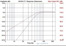
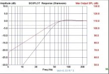
I ran some simulations on likely suspects. Three particularly interesting ones are the Dayton titanic 10", the Dayton HO 10", and the TB 8x12". All of them simulate as being able to hold up to nearly 100dB at 30Hz in boxes ranging from 0.25 ft^3 ti 0.5 ft^3. Of course in boxes this small the driver's volume is a significant portion of the total so the actual dimensions would be noticeably larger than one would imagine but still quite manageable in my application.
The titanic has substantially more Xmax at over 19mm v.s 12mm on both of the others but the simulation seems to indicate that they are not really Xmax limited as the max output is not drastically different. I know that this software will show Xmax limited output as I have run into it before.

The TB 8x12: This is very good results given the reasonable cost for the driver and it's convenient shape. I used the same cone diameter (9") for this simulation as I did for the other two. I wasn't sure what the actual equivalent cone diameter for an 8x12 would be but I figured it would be close to that of a 10" as 6x9 is close to an 8".

The High Output: Right now I like this one the best as it levels off a little higher up in the frequency spectrum and I really don't want to cross the mains over any lower than 80Hz. On all of these we could look at making the box even smaller to drive the crossover up but the effect is minimal and we haven't much room to go much smaller. In order to go much farther up I would have to use drivers with higher fs.

And the Titanic: Good but not really better than the others. It may have less distortion however (almost certainly true compared to the TB) but the crossover point is getting pretty low.
mike
The titanic has substantially more Xmax at over 19mm v.s 12mm on both of the others but the simulation seems to indicate that they are not really Xmax limited as the max output is not drastically different. I know that this software will show Xmax limited output as I have run into it before.
The TB 8x12: This is very good results given the reasonable cost for the driver and it's convenient shape. I used the same cone diameter (9") for this simulation as I did for the other two. I wasn't sure what the actual equivalent cone diameter for an 8x12 would be but I figured it would be close to that of a 10" as 6x9 is close to an 8".
The High Output: Right now I like this one the best as it levels off a little higher up in the frequency spectrum and I really don't want to cross the mains over any lower than 80Hz. On all of these we could look at making the box even smaller to drive the crossover up but the effect is minimal and we haven't much room to go much smaller. In order to go much farther up I would have to use drivers with higher fs.
And the Titanic: Good but not really better than the others. It may have less distortion however (almost certainly true compared to the TB) but the crossover point is getting pretty low.
mike
Attachments
Last edited:
The titanic has substantially more Xmax at over 19mm v.s 12mm on both of the others but the simulation seems to indicate that they are not really Xmax limited as the max output is not drastically different.
The High Output: Right now I like this one the best as it levels off a little higher up in the frequency spectrum and I really don't want to cross the mains over any lower than 80Hz.
Right, as the driver excursion increases, the cab's compliance decreases, so if the driver 'feels' more power than the cab's willing to let the driver use it just (over) heats the VC, raising Qts, Qtc and potentially damaging the driver if there's no high pass protection.
Use an LR4 XO and you can probably get away with a 1.4 Qtc alignment, further reducing cab size and/or allowing a driver that will net more peak gain BW for a given net Vb.
GM
Are we talking about the same systems here??
Rods board has high pass filter built in, usually set at between 12 and 18Hz, between there and whatever lowpass you select the comparator increases the signal to the amplifier at +6dB per octave.
So if your main system rolls off below Fc ( say 80Hz -6dB at 60? then the ELF system starts at Fc-6dB 60Hz ) and between 60 and 18hz the you get that increase in signal.
So X-max is very important as excursion must surely increase dramatically as the signal approaches the lower limit of the board.
This is why as I investigate the use I have decided to go with multiple woofers rather than 1 big one.
So modeling as a standard sealed box surely won't tell you how that driver will perform in an ELF system, instead I would just see how much power you need to handle the increased signal to get that maximum excursion.
The modeling software gives two graphs. One is the response graph that we are used to seeing which just tells us how the system will respond to a constant moderate signal as the frequency is swept. This shows the 12dB/8va roll off that we normally see with a sealed enclosure. Our LP filter will be compensating for this so that the output will be nominally flat down to the turn over frequency of our LP. Below this point the output will resume falling at 12dB/8va. Unfortunately the software does not have a way to show the results of the compensating LP filter.
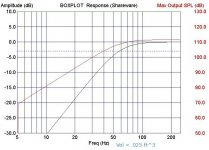
The other trace shows the maximum SPL output at various frequencies. This takes into account the Xmax in combination with cone area and the maximum power dissipation rating. In the past when I have model drivers in an enclosure that was Xmax limited there was an obvious discontinuity where that limitation kicked in. In these graphs I am not seeing an obvious indication of that. It is possible that it is there but just not obvious.
The titanic is rated at 400W and 19mm Xmax while the HO is rated at 600W and 12mm. The maximum output graphs are nearly identical in similar box sizes. The HO is modeled with a slightly smaller enclosure but its Vas is also slightly less. The HO in fact holds out a couple of dB better at 5Hz than the Titanic.
This leads me to believe that it is indeed as we had predicted that the high damping of the small enclosure is limiting the excursion at lower frequencies and so the limiting factor is becoming the voice coil dissipation. So the expected failure mode would be a burned voice coil rather than physical bottoming with either driver and we don't really gain any output in this particular case by going with the Titanic as you would in a more normal alignment.
Now the thing to watch for is that if the amplifier is capable of providing more power than the driver can stand and there is no infrasonic filter it would be quite possible to burn up the driver. We also have to take into consideration that the small enclosure is not a conducive to cooling of the voice coil and the full power handling capability will probably be compromised thereby. Our concerns in this case are just the opposite of what they would be in the design of say a tapped horn.
All that being said this application is a portable iPod system and not a full size home theater application so we don't really need house wrecking output. I figure on shooting for flat response to around 30Hz with HP below that and limiting the sub amp to 200-300W at most so any of the drivers should survive just fine.
Of course this is all modeling. The proof is in the building.
You know i haven't yet tried this myself; even though I bought the board a year ago; so I have no direct experience.
But if all you are after is -6dB at 30 Hz the a small standard plate amp is probably going to suit you space requirements better if an 8inch sub is what you have and close listening is what you need
But if all you are after is -6dB at 30 Hz the a small standard plate amp is probably going to suit you space requirements better if an 8inch sub is what you have and close listening is what you need
Thanks Moondog. This system is a gift so I will be using all new parts. I just plan on doing a little proof of concept with the little 8"er I have. I will probably end up using a plate amp for the subwoofer power with my own filtering in front of it. A lot of plate amps have the infrasonic filter included so I would only need to do the compensation filter which is pretty simple.
The rest of the electronics will be vacuum tube so in order to keep PS simple I may use high voltage FETs for the filter so I can just use the B+ from the main amp. The other option would be to hack into the plate amp and pull power from there for the filter but I don't really relish that option. I have considered using some sort of class D module and doing all of the filtering and control myself but that seems like a waste of effort when so many suitable plate amps are available. What I plan to do is to imbed the plate amp inside the back so that the rear cover must be removed to adjust crossover and gain and then put a level control in my filter circuit which will be the bass control on the users control panel.
I could use a vacuum tube filtering circuit but since the chassis is going to be practically on top of the subwoofer enclosure I am inclined to keep the sub signal all sand to avoid any issues with microphonics.
- Status
- Not open for further replies.
- Home
- Loudspeakers
- Subwoofers
- Need info on operating below Fc