Hi all,
I usually figure things out pretty well but this one has me stumped. This is part of the Tremolo LFO in a Sears Silvertone 1484 guitar amp, and as you can see it is not of the ordinary LFO circuits. Maybe someone can shed some light for me and help me understand this one. The circuit consists of a 12AX7 where one section is the LFO and the other they are using for the noen light driver, which is part of a opticoupler. All values are in Mf and even though the schematic shows 205v for pin 8 plate voltage it actually measures 320v. I think this is print a error due to the fact that R53 (330K) is fed by the 340v 6L6 grid supply. Cheers
I usually figure things out pretty well but this one has me stumped. This is part of the Tremolo LFO in a Sears Silvertone 1484 guitar amp, and as you can see it is not of the ordinary LFO circuits. Maybe someone can shed some light for me and help me understand this one. The circuit consists of a 12AX7 where one section is the LFO and the other they are using for the noen light driver, which is part of a opticoupler. All values are in Mf and even though the schematic shows 205v for pin 8 plate voltage it actually measures 320v. I think this is print a error due to the fact that R53 (330K) is fed by the 340v 6L6 grid supply. Cheers
Attachments
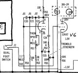
The bias arrangement is a little different from what I am used to seeing. Actually this is the first time I have delt with a LFO oscillator so I am in the learning stage. And of course the fact that it doesn't work. I just wanted another opinion because there are a few miss prints on this schemematic. Actually when I got this amp someone had wired it R56 to B+ pin 8, then tied them to ground. Now way this would have worked. Also all the designs I have seen so far go with 300v plate voltage and this circuit shows 205? I just like to know a little theory before swapping parts out. I do know the Neon lamp is very weak but shouldnt I still get the oscillator to work? Cheers
Toobstheway said:The bias arrangement is a little different from what I am used to seeing.
Actually, that's the 'normal' method of biasing, in use before auto-biasing via a cathode resistor appeared.
I'm presuming you've checked the 330K anode load resistor?, that's a very common fault in valve gear, going high or O/C.
Figured it out!!
Even you pro's missed this one. Look at the schematic real close and notice plate and cathode pins labeled wrong! Just goes to show you can't always trust schemo's you get on the net. I did however learn a lot about how oscillators work and how do design them, so over all a positive learning experience. Cheers
Even you pro's missed this one. Look at the schematic real close and notice plate and cathode pins labeled wrong! Just goes to show you can't always trust schemo's you get on the net. I did however learn a lot about how oscillators work and how do design them, so over all a positive learning experience. Cheers
Why would having the pin numbers printed wrong on the diagram stop it working?, it's also uncommon to even have them on diagrams.
When I initally got the amp, it was in shambles and needed to be wired up and I went by the schematic, which in turn led me to wire it up wrong. And of course therefore it wouldn't work.
- Status
- Not open for further replies.
- Home
- Live Sound
- Instruments and Amps
- Need help with Tremolo LFO!