I've been reading about them (link here) and realized that the Darling amps are geared to sounding pretty good and not costing much. I've never build a high voltage tube amp before (but I have worked with high voltage before), though I have built a few low-voltage designs with 6GM8 and the like. When I go into unknown territory, I don't want to spend a lot. I have several transformers laying around, which I used the specs of for the circuit shown in the attachment.
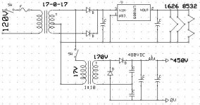
I have a 24V, 40VA to 0V-120V-208V-240V transformer and a 17-0-17V transformer that I thought I could probably use most effectively. They are pretty much new. I planned on using the 17V first up as input to feed the 24V taps on the second transformer and also to power the heaters. I prefer DC heaters, so I went with a 12V regulator (ignore the part number in the circuit) and caps to feed the two 1626's in parallel and the two 8532's that are in series with one another (but parallel with the 1626's). One 17V wire and the ground connection then connect to the second transformer on the 24V taps, which steps up in a 10:1 ratio to make 170V and 0V that I feed into a voltage doubler, which then effectively becomes 480V after rectification. I then just drew in the standard PS for the DC Darling.
What I really want to make here is the parallel SE DC Darling (DC Double Darling shown onthis page). It requires about 400V, so I'll probably have to drop the supply a little more with another LC or RC filter.
I'll have more questions later... if this looks like it will work ok. One thing I am worried about is the heater-cathode voltage difference I saw a note of somewhere. The difference cannot be more than 100V or so I think I saw. Have I managed to take this into account with my PS design? I'm slightly lost here...
Thanks all 🙂
That PSU looks pretty good to me. Just be sure you don't exceed either of the trafos VA ratings or the step up's insulation capabilities. You don't need the cap. across the doubler stack. Make the doubler stack caps. LARGE. The trafo driving the doubler needs to be able to yield an AC RMS current 4X the doubled DC voltage draw.
I am not so sure this is working correctly... I rigged it up for a test as shown (but without the diodes and such- just AC voltages) and am getting very strange voltages. The 120V line gives about 60V, the 208V gives 58V, the 240V gives 70V. Something must be wrong here... Am I missing something about coupling transformers together?
Ok, I rewired and tried again.
I put 120V on the primary of the multi-tapped transformer and got the full 208V and 240V as well as the 24V secondary. Maybe I can just use this transformer without the other one... It's kind of small, though. I worry it doesn't have enough current drive. How much does the DC Double Darling draw, anyway?
I put 120V on the primary of the multi-tapped transformer and got the full 208V and 240V as well as the 24V secondary. Maybe I can just use this transformer without the other one... It's kind of small, though. I worry it doesn't have enough current drive. How much does the DC Double Darling draw, anyway?
My biggest question at the moment...
I've seen people use low power transformers as SE output transformers. Can I do this with the Darling amp? It seems reasonable, given the low power. I found an amp using the 6EM7 that used a 12-0-12V at 3A power transformer as the output tranny... I thought maybe I could use the a 2A or 3A model for this amp to drastically cut down costs. I know it won't sound as good... but surely it will sound pretty good.
I have a fear of spending a lot of money on something that I am unsure will work the way I want it to. That is why I am reluctant and wanting to cheap out on everything...
I am confused about primary impedence, though. When I measure transformers I have around here, they have a VERY low resistance. The 6EM7 project calls for a 3.2k transformer and he is able to use the power transformer there. What is the change going on there?
Thanks
You measured the DC resistance of the windings.
The impedance ratio of a trafo varies as the square of the turns ratio. For instance: if a 10 Ohm load is connected to the secondary of a 10:1 trafo, the impedance reflected at the primary is 1000 Ohms.
The impedance ratio of a trafo varies as the square of the turns ratio. For instance: if a 10 Ohm load is connected to the secondary of a 10:1 trafo, the impedance reflected at the primary is 1000 Ohms.
- Status
- Not open for further replies.
- Home
- Amplifiers
- Tubes / Valves
- Need help with PS for 1626 "Darling" amp