Hello All,
I don't post often but enjoy lurking and trying to learn a little more about everything.
Recently I picked up the above TT for cheap, knowing it had issues. I am hoping to save this machine but will need your help pls.
From what I can gather, the TT hasn't got the required voltages for proper operation. As I was confident to recap this myself I have done so, but no change unfortunately. I am confident I have made a proper job of this but I will look over all I did again to be sure.
I suppose I'm asking for some basic direction here. Being a fully auto TT each function seems to feed the next. This is made more difficult by the incorporation of prism/sensors that detect 1. record present on the platter, and 2. record size.
If I can determine what is wrong and an idea of what it might cost to get up and running then I'm happy to either do the work myself (if a relatively straight-forward fix), or take this to a tech for a service/repair.
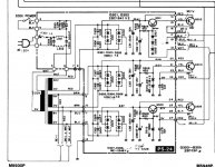
I'll post a schematic of the power board and pic of the transformer arrangement shortly.
It goes without saying, I appreciate any help on this.
Dennis
I don't post often but enjoy lurking and trying to learn a little more about everything.
Recently I picked up the above TT for cheap, knowing it had issues. I am hoping to save this machine but will need your help pls.
From what I can gather, the TT hasn't got the required voltages for proper operation. As I was confident to recap this myself I have done so, but no change unfortunately. I am confident I have made a proper job of this but I will look over all I did again to be sure.
I suppose I'm asking for some basic direction here. Being a fully auto TT each function seems to feed the next. This is made more difficult by the incorporation of prism/sensors that detect 1. record present on the platter, and 2. record size.
If I can determine what is wrong and an idea of what it might cost to get up and running then I'm happy to either do the work myself (if a relatively straight-forward fix), or take this to a tech for a service/repair.
I'll post a schematic of the power board and pic of the transformer arrangement shortly.
It goes without saying, I appreciate any help on this.
Dennis
Attachments
Last edited:
That was super fast rayma. Thank you for posting the full link.
To start, measure the supply voltages on the PS-24 pcb at #17, #23, and #27, with respect to ground #18.
Should be 24VDC, 12VDC, and 5VDC.
Last edited:
Thanks rayma,
I'll need to reconnect the transformer... disconnected secondaries to measure unladen supply;
Results, unladen
240v/50Hz,
8v tap measured 7.2v
18v tap measured 14.85v
27v tap measured 20v
Voltages when tx connected;
8v tap measured 7.95v
18v tap measured almost open
27v tap measured 20.3v
Measurements as requested to come later.
cheers
Well that's weird, the voltages shouldn't be going *up* when you connect the load...
By "open" for 18v, what do you mean
By "open" for 18v, what do you mean
To start, measure the supply voltages on the PS-24 pcb at #17, #23, and #27, with respect to ground #18.
Should be 24VDC, 12VDC, and 5VDC.
Ok here we go.
#17 - 1.8VDC
#23 - 7mVDC
#27 - 5.9VDC
This is with the wiring from the tx to PS-24 pcb as I bought it.
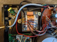
Looking at the schematic though, the brown wires appear reversed. The schematic shows 18V to #9, 0V to #10 so I tried reversing the browns but the tx seemed to get hot quickly. So it's back to how I found it.
Thanks
Some points to note,
The unit I have is 250V/50Hz according to the label on the TT.
The schematic shows a 110V/60Hz supply.
I also promised to post a pic up of the tx. Something that looks odd to me is the 18V brown secondary with the 0V tap on the primary side and the 18V on the secondary. Perhaps this is just an odd winding pattern/configuration but I thought I would just point it out.
Of course, to those offering help and advice a big thank you!
cheers
Attachments
> The unit I have is 250V/50Hz according to the label on the TT.
> The schematic shows a 110V/60Hz supply.
All three places the schematic says "120V" have a halo like someone pasted-in a change. Like 240V is the base design, a 120V model was sold in the US, and the scan was taken from a US manual.
Your transformer shows a "240V" winding so you are probably OK.
> The schematic shows a 110V/60Hz supply.
All three places the schematic says "120V" have a halo like someone pasted-in a change. Like 240V is the base design, a 120V model was sold in the US, and the scan was taken from a US manual.
Your transformer shows a "240V" winding so you are probably OK.
Attachments

#17 - 1.8VDC
#23 - 7mVDC
#27 - 5.9VDC
Seems to be a problem there. What's the DCV at #14, #20, and #24 wrt #18 ground?
Do you get any DC voltage on C313/R305?
I suspect you might have a short on the +12V somewhere that's pulling everything down.
If it's not too much hassle, try disconnecting the RED wire at #23 and measuring again. You can also try measuring resistance to ground at this spot before/after (with power off).
BTW, the solder joints on the transformer primary look a bit crusty to me, the 0 V in particular. That clearly wouldn't be helping matters. Any change of output voltage if you wiggle the cable? A bit of flux and fresh solder may be appreciated.
Is the power switch delivering a decent enough contact resistance?
A flaky primary connection or power switch are about the only reasons I can think of for why unloaded voltages were higher than loaded. Well, either those or a flaky thermal fuse... At times these have been known to go bad all by themselves, but here the potential short on +12V might just have sort of degraded it. Maybe try getting a resistance reading on the primary and observing whether tapping the xfmr changes anything.
Worst case would be some shorted turns. That would make the transformer get quite warm though.
PBR said:All three places the schematic says "120V" have a halo like someone pasted-in a change. Like 240V is the base design, a 120V model was sold in the US, and the scan was taken from a US manual.
Your transformer shows a "240V" winding so you are probably OK.
Yesterday 08:32 PM
Thank you. Nice to know the unit is unmolested.
Seems to be a problem there. What's the DCV at #14, #20, and #24 wrt #18 ground?
Here we go!
#14 - 25.7VDC
#20 - -21.6mVDC
#24 - 5.82VDC
cheers
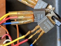
Ok just following the path from #14, 20 & 24 and they lead to this!
Are you kidding me? Those tabs can't touch anything, they're all at different potentials.
Last edited:
No joke rayma. I just followed the power to these 3 transistores and found what I found.
if it's any consolation they were sheathed in old plastic tubing.
if it's any consolation they were sheathed in old plastic tubing.
No joke rayma. I just followed the power to these 3 transistores and found what I found.
if it's any consolation they were sheathed in old plastic tubing.
Does that look original, or did someone do that after the fact? Terribly shoddy practice.
Check them unpowered with a dvm on the diode function. At least one is good.
Last edited:
Can I still buy these or is there any replacements?
https://datasheet.octopart.com/2SD330-Inchange-Semiconductor-datasheet-15979812.pdf
Bipolar Transistor Cross-reference Search | Equivalent Transistors
Last edited:
Does that look original, or did someone do that after the fact?
Terribly shoddy practice.
DIATONE DP-EC1
The pi8c there shows a mounting panel for these in the bottom right corner. I suppose I could fashion something to secure them.
Generally, I get the impression someone else has been in and around the power side of things.
- Home
- Amplifiers
- Power Supplies
- Need help with power supply: Diatone DP-EC! turntable.