hi there
fuseible resistors are also flame proof
see here http://www.answers.com/topic/fusible-resistor?cat=technology
regards
bob
fuseible resistors are also flame proof
see here http://www.answers.com/topic/fusible-resistor?cat=technology
regards
bob
i looked it up on google 🙂 for testing i think
the one i put there should work.
I replace it later.
It didnt work with the capacitor change =/
This was a hard one to crack 😛
But tell me why does the amp power up
when i removed that resistor?
the one i put there should work.
I replace it later.
It didnt work with the capacitor change =/
This was a hard one to crack 😛
But tell me why does the amp power up
when i removed that resistor?
hi
this resistor is a dropper resistor feed ing the output relay circuit.
i will scan the diagram for you in a few days,
have you got test equipment?
regards
bob
this resistor is a dropper resistor feed ing the output relay circuit.
i will scan the diagram for you in a few days,
have you got test equipment?
regards
bob
Okay it would be great!
I have a digital multimeter.
also have an old analog somewhere.
And an old storage scope, but works fine.
Dont have the knowlegde how to use it.
just basics.
Any tips what to look for? Can i use my
scope to check some components like
the transistors?
Thanks again! =)
I have a digital multimeter.
also have an old analog somewhere.
And an old storage scope, but works fine.
Dont have the knowlegde how to use it.
just basics.
Any tips what to look for? Can i use my
scope to check some components like
the transistors?
Thanks again! =)
Now i really messed it up!
I was going to put the driver transistors
back into the board.
And i think one of the legs got stuck
and lifted the pad of the board.
I tryed to pull it down and weld it
but the hole thing fell of.
Now i dont have any pad to weld the
transistors leg to =/
Is there any good way to fix this?
Manage to get a connection to the
trace anyway but dont now if it will
hold.
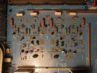
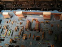
If you use a small jumper wire like the one in the image below (leg from a 1/4 watt resistor), it will be reliable. Scrape the solder mask off of the trace and solder the wire to it. Try to go back far enough to reach another solder pad (for added strength). On this board, the original trace ends at the green arrows. The wire is soldered to entire length of the trace.


hi
it will be a few days sorry, please be patient.
perry nice description and great pic
regards
bob
it will be a few days sorry, please be patient.
perry nice description and great pic
regards
bob
dont panic- im just glad if i get it 😉
Where did you find the manual anyway?
Have searched my eyes of on the internett.
Cant find the c350.
C302 C352 C370..i found all modells
execpt c350, strange
Where did you find the manual anyway?
Have searched my eyes of on the internett.
Cant find the c350.
C302 C352 C370..i found all modells
execpt c350, strange
do you have the time to scan the schematic?
thats the most important thing 🙂
would help me alot, i think 😛
thats the most important thing 🙂
would help me alot, i think 😛
This is the case, by mistake I swapped one of the
drivers and the fuses blew.
And now some parts getting warm, i have removed a lot
of componets checking them for shorts.
The big Outputs i desolder, they are just screwed to
the heatsink pins 4mm over the board.
Havent found any bad componet yet.
But something is wrong.
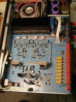
I have marked 4 resistors, they get very hot
after just 1 minute. Strange.
Even after removing that much componets as you
can se on the picture.
None of the smaller transistors get hot.
Just two of them, but i removed them and they
are ok. Resistors still get Hot!
Everything so far is OK.
What should i do!? This makes no sense.
All the diodes are OK.
I do not understand why the resistors get so hot.
Bic current, but from where?
Anyone?
Attachments
I don't have the schematic for the C350 but looking at the one for the C320, I'd guess that the resistors are connected in series with the 4.7v Zener diodes. This would mean that current would be flowing through them whenever the amp is powered up. They used large resistors because they are required to dissipate significant power. This means that they will run hot normally.
They appear to be 2 watt resistors. Measure the voltage across them and use the formula P=E^2/R to determine if they're dissipating more power they they should be.
Unless the Zeners are shorted, It's unlikely that they're running hotter than normal.
Didn't you previously have one working channel?
They appear to be 2 watt resistors. Measure the voltage across them and use the formula P=E^2/R to determine if they're dissipating more power they they should be.
Unless the Zeners are shorted, It's unlikely that they're running hotter than normal.
Didn't you previously have one working channel?
ok but after 1 minute my i burn my fingers if
i place my fingertip on them for a couple of seconds.
And i think it got worse after removing some
components.
But what is the most likely think that have blown?
Something has happend. Any tips? 🙂
Just looking at the board what would you do?
Regards Stefan
i place my fingertip on them for a couple of seconds.
And i think it got worse after removing some
components.
But what is the most likely think that have blown?
Something has happend. Any tips? 🙂
Just looking at the board what would you do?
Regards Stefan
Have you checked the output transistors to determine if they've survived?
Do you have exact replacements for the driver transistors that failed?
Did you build the current limiter?
Do you have exact replacements for the driver transistors that failed?
Did you build the current limiter?
hi
be patient with regard to the diagram i will get it done soon.
tips
wait for the diagram
dont swap bits from the good channel, other wise you will have double trouble
dont power the thing up until you have checked most of the components in the output stage, all semiconductors resistors etc
you will need to unsolder them to get acurate readings
in the meantime you could find out how to test semiconductors with your meter, and check them
also compare the readings of each with the good channel
regards
bob
Ok, i wil be patience with the schematic 😉
Tonight i will check the transistors. ALL of them.
Some soldering to do.
Question. found 4 ICs.. with the same casing
as transistors. the small ones with 3 legs.
WL431 CPL.. cant find any datasheet.
Have a feeling that they are defect.
TL431 CPL, maybe its the same but
another manufacter??
Tonight i will check the transistors. ALL of them.
Some soldering to do.
Question. found 4 ICs.. with the same casing
as transistors. the small ones with 3 legs.
WL431 CPL.. cant find any datasheet.
Have a feeling that they are defect.
TL431 CPL, maybe its the same but
another manufacter??
- Home
- General Interest
- Car Audio
- Need help with NAD amp! Goes in protection


