A quick introduction of myself, I have been lurking around for ages but just recently joined the forum. I wanted to learn electronics badly when I grew up but never managed to get by the basics is school. But I did learn to program and that is what I do for a living when I'm not tinkering with vintage hifi gear.
I am planning to build my first speakers this summer and just recently got obsessed by Gainclone when I was doing research on the net. I know this might not be the best idea but I could not stop myself having this ideas about making my own amplifier (already built my own music streamer and DAC and soon my own speakers).
It seems like most Gainclone builders prefer the minimalistic approach with no tone control or at least an external preamp. I sat down and thought about what I wanted in my system and what I could do without. A couple of line inputs, the ability to switch speakers on and off and headphone support. Volume of course but no need for balance. I do want tone control but I have no need for things like loudness if the tone control is flexible enough. That is where I got mesmerized by the variable frequency LF and HF shelving EQ by Douglas Self (Small Signal Audio Design, Chapter 15).
I first stumbled on this circuit when following a reference to the article “A low-noise preamplifier with variable-frequency tone controls” published in Linear Audio Vol 5, April 2013. I also found more than one reference to it here at this forum. But I found it a bit to complex for my use case with balanced in- and output, balance control etc. I also wanted full placement freedom of pots etc. on my front panel. I started to think to myself, what if I could make a less complicated version of this circuit for my integrated Gainclone? Now this is where the real challenge started. I knew little about electronics, nothing about circuit design and PCB construction. But I am a good learner and extremely stubborn. I am also surrounded by electronics- and hifi nerds at work but I felt that I had to do most of the legwork myself.
I gathered as much background material as possible and started to read through it. I also downloaded every free PCB design software I could find. I tried Eagle and KiCad before I finally settled for DipTrace. I browsed through the tutorial and used my Simple LF and HF shelving Preamp project to learn more about it. It took me almost three days to crank out my first schematics, PCB and BOM. I borrowed loads from the work by Douglas Self (mostly from his book Small Signal Audio Design) but also from numerous threads on this forum (thanks Carl_Huff for putting together a BOM for the full Precision Preamp I borrowed most of my BOM from it).
But this is the end of the road for me. I have made guesses and assumptions. I now need some real knowledge. I therefor humbly ask for second opinions. What have I done wrong (can line input, tone control and volume control really be stitched together the way I have done it)? What about my PCB? I have never done anything like it before so please be gentle 😉
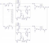
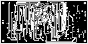
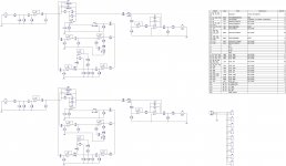
Attached are printouts of my "home brew" schematics, PCB top- and bottom layers and BOM.
Thanks in advance for your feedback and constructive criticism / Robert
I am planning to build my first speakers this summer and just recently got obsessed by Gainclone when I was doing research on the net. I know this might not be the best idea but I could not stop myself having this ideas about making my own amplifier (already built my own music streamer and DAC and soon my own speakers).
It seems like most Gainclone builders prefer the minimalistic approach with no tone control or at least an external preamp. I sat down and thought about what I wanted in my system and what I could do without. A couple of line inputs, the ability to switch speakers on and off and headphone support. Volume of course but no need for balance. I do want tone control but I have no need for things like loudness if the tone control is flexible enough. That is where I got mesmerized by the variable frequency LF and HF shelving EQ by Douglas Self (Small Signal Audio Design, Chapter 15).
I first stumbled on this circuit when following a reference to the article “A low-noise preamplifier with variable-frequency tone controls” published in Linear Audio Vol 5, April 2013. I also found more than one reference to it here at this forum. But I found it a bit to complex for my use case with balanced in- and output, balance control etc. I also wanted full placement freedom of pots etc. on my front panel. I started to think to myself, what if I could make a less complicated version of this circuit for my integrated Gainclone? Now this is where the real challenge started. I knew little about electronics, nothing about circuit design and PCB construction. But I am a good learner and extremely stubborn. I am also surrounded by electronics- and hifi nerds at work but I felt that I had to do most of the legwork myself.
I gathered as much background material as possible and started to read through it. I also downloaded every free PCB design software I could find. I tried Eagle and KiCad before I finally settled for DipTrace. I browsed through the tutorial and used my Simple LF and HF shelving Preamp project to learn more about it. It took me almost three days to crank out my first schematics, PCB and BOM. I borrowed loads from the work by Douglas Self (mostly from his book Small Signal Audio Design) but also from numerous threads on this forum (thanks Carl_Huff for putting together a BOM for the full Precision Preamp I borrowed most of my BOM from it).
But this is the end of the road for me. I have made guesses and assumptions. I now need some real knowledge. I therefor humbly ask for second opinions. What have I done wrong (can line input, tone control and volume control really be stitched together the way I have done it)? What about my PCB? I have never done anything like it before so please be gentle 😉
Attached are printouts of my "home brew" schematics, PCB top- and bottom layers and BOM.
Thanks in advance for your feedback and constructive criticism / Robert
Attachments
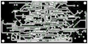
Seems like I cant edit my previous post after 30 minutes, wounder why? Anyway I browsed further into the DipTrace tutorial and discovered some info about track width and copper pours. So I made the tracks wider, 0.5 mm, is that enough? And added copper pours attached to ground, is that good or bad? It sure looks neat 😉
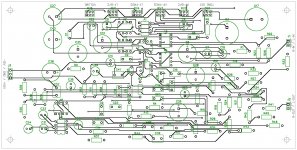
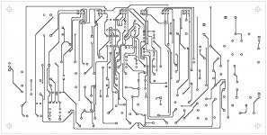
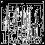
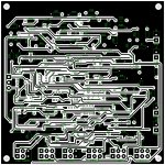
Attached are printouts of the new PCB front and back...
Attached are printouts of the new PCB front and back...
Attachments
Last edited:
For most posts the limit for editing is set to 30 minutes by forum policy. You should still be able to edit your first post which I recommend you do with great care. (Never delete!)
Feels a bit like I'm talking to myself but here is an update. I live in Sweden so I had to convert my BOM from Mouser to Farnell. I spent the last 24 hours going through my schematic component by component. I found several errors in my initial attempt and I also took the time to analyze each component from a price/performance/size standpoint. I then tried different sizes of the board and placement of solder pads for board connections. I finally ended up with a 150x150 mm board. I also spent some time going back to Douglas Self's texts and there is a lot of information about each circuit and its components. I still got some questions though:
/ Robert
- I routed the board with 0.7 mm trace width and 0.5 mm clearance, good or bad?
- I added copper pours connected to ground on both sides, good or bad?
- Does the schematics and PCB make sense in general?
/ Robert
Attachments
Your PCB looks impressive.
I've used DipTrace for several boards and the one comment I would make is that when you see the board for real, those traces and pads will look very very tiny and fragile.
This is the sort of sizes I tend to use.

Welcome to diyAudio by the way 🙂
I've used DipTrace for several boards and the one comment I would make is that when you see the board for real, those traces and pads will look very very tiny and fragile.
This is the sort of sizes I tend to use.
Welcome to diyAudio by the way 🙂
What sizes are they (trace width, pad size, vias etc.)? Do you know? I tried 1 mm track width but I probably have to make the board bigger to make it work with the auto-placement and router (I lack the skill to place and route manually). That's why I try to figure out sane defaults for trace width (I have never made a PCB before), especially for this use case (preamp, I don't know whats "normal"). DipTrace is growing on me. Super easy to get going and to make your own component libraries including patterns. I just wish it was a native OS X application... 😉Your PCB looks impressive.
I've used DipTrace for several boards and the one comment I would make is that when you see the board for real, those traces and pads will look very very tiny and fragile.
This is the sort of sizes I tend to use.
Thanks! 🙂Welcome to diyAudio by the way 🙂
Ps. I managed to reroute the card with 0.9 mm trace width but 1.0 mm requires a new placement...
Last edited:
The thinnest trace widths are around 1.2mm
These are the IC pad and Resistor pad sizes that I use.


These are the IC pad and Resistor pad sizes that I use.
Thanks a lot Mooly, just what I needed! 🙂🙂🙂The thinnest trace widths are around 1.2mm
These are the IC pad and Resistor pad sizes that I use.
Back to PCB Layout...
Ps. What trace width is needed in an preamp for audio signal and power in general? Would 0.9 mm work?
Last edited:
You should be able to edit your board manually. Save it under a new name and then you have the original as a backup. You can select groups of parts and alter the pads at a group level so that they all change at once. Trace widths are easily editable too although its a bit time consuming.
Good luck 🙂
Good luck 🙂
- Status
- Not open for further replies.
- Home
- Source & Line
- Analog Line Level
- Need help with "my" Simple LF and HF Shelving Preamp