I am currently in the process of building my Mechano23 speakers.
So far everything has been going decently smooth. However, before entirely sealing the box I wanted to test the crossovers.
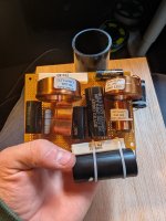
When testing the speakers everything was working fine. However, with the the box sealed using clamps and the crossover attached to the box. I noticed the tweeter started making a cracking noise when playing at higher volumes. After some re-adjustments of the joints I noticed the mid woofer was doing the same and the cracking in the tweeter had almost entirely stopped. After some thinking I presume that the issue is caused by a combination of bad joints on my crossover and internal vibrations.
The attached image was taken before the entire circuit was soldered. But for all the joints I twisted and then soldered the wires.
Could anyone provide some tips or help on how others have tackled this issue? I want these speakers to last a long time, so I want to make sure I do it right.
Thanks for the help!
So far everything has been going decently smooth. However, before entirely sealing the box I wanted to test the crossovers.
When testing the speakers everything was working fine. However, with the the box sealed using clamps and the crossover attached to the box. I noticed the tweeter started making a cracking noise when playing at higher volumes. After some re-adjustments of the joints I noticed the mid woofer was doing the same and the cracking in the tweeter had almost entirely stopped. After some thinking I presume that the issue is caused by a combination of bad joints on my crossover and internal vibrations.
The attached image was taken before the entire circuit was soldered. But for all the joints I twisted and then soldered the wires.
Could anyone provide some tips or help on how others have tackled this issue? I want these speakers to last a long time, so I want to make sure I do it right.
Thanks for the help!
Attachments

Hi Joris,
Inductors usually have the ends of their wires tinned (with a small amount of solder) when you buy them, but if you cut the ends off (say, if you've removed a few turns to tweak the coil value) you have to take the enamel off the freshly cut wires to expose the copper before re-soldering them.
Is there a chance you may have left enamel on any of them?
Just a thought due to the method you've used to mount and connect them under the board by twisting and soldering.
Cheers
Stuey
The wires on inductors are rather large. Even if the enamel is scraped off, your soldering iron may be too low in watts to make a normal joint. Cold joints lose contact when vibrated. A speaker can vibrate everything inside. I would use at least a 70 w iron with temperature control feature. One brand is Hakka, although I find them rather expensive compared to the one that I use from parts-express.com . Shipping from P-E would be prohibitive to Europe, so ask around for another supplier. A wider tip than the pointy one original to the iron,a 2 or 3 mm chisel tip, also helps solder bigger wires.

You should get a bigger board, redo and clean the wires before soldering, trim the passive parts
solid wire so it protrudes through the board as if it were a normal pcb and wire parts with a hook-up wire.
solid wire so it protrudes through the board as if it were a normal pcb and wire parts with a hook-up wire.
@indianajo I was soldering at a decently low temperature because I was afraid of damaging components due the high heat. But thanks for the tip! I think I will redo the crossover and ensure all connections are soldered at high heat taking in mind the enamel coating on the inductors.
For bigger parts like inductors that suck the heat out of the iron, I just use a cheap 60 watt unregulated iron with a chisel tip. It gets stupidly hot and is pretty much only good for this kind of thing - in fact, I have to turn it off sometimes if I'm not using it constantly because it burns the flux. But the tip is quite big and holds a fair bit of heat.
I have two soldering stations and multiple different tips (48w and 60w) but the cheapy is more effective for big copper.
I have two soldering stations and multiple different tips (48w and 60w) but the cheapy is more effective for big copper.
+1You should get a bigger board...
Tying a power resistor and a capacitor together is a big no-no.
I'm tired of saying the same thing...
keep the crossover out of the box.
Do the biwiring thing
Just for starting
keep the crossover out of the box.
Do the biwiring thing
Just for starting
Did you measure the tweeter response by its self with the x-over, to verify the roll-off?@temp25 I have measuring equipment. I can say for certain that there arn't any shorts in the circuit, and I am fairly certain everything is wired correctly.
Eventhough it will be lots of work, I will remake the crossover and spread the parts a little more.
Thanks you for the reply!
Have you assembled the second x-over for the other speaker?
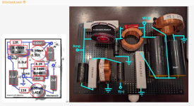
I just noticed. That 1.5mH coil is in the worst possible orientation to the .56mH coil. Maybe you can rotate the smaller coil 90 degrees, and see if that was the problem.
Last edited:
That would also be when current through the coil is high, and more likely to affect the other coil.
That's a small box. It's often a tight fit for a x-over. Is there any chance there is stress being applied to the x-over board by a part contacting a box wall, or magnet.
That's a small box. It's often a tight fit for a x-over. Is there any chance there is stress being applied to the x-over board by a part contacting a box wall, or magnet.
Coil interaction can cause crossover curves shifted in frequency or slope from the design and simulation. It will not cause pops. Sudden interruptions of current will cause pops. Such can be caused by defective parts (unlikely), shorts in a burned paper board (not too likely) or bad connections (very likely). If you want to protect the components from a very hot iron, leave as much lead length as you can stand. A hot iron will act quicker, and thus less heat will flow up the wire to the component.I just noticed. That 1.5mH coil is in the worst possible orientation to the .56mH coil. Maybe you can rotate the smaller coil 90 degrees, and see if that was the problem.
Clean up the board afterwards with isoprophyl alcohol and a cotton ball. A certain very experienced professional posted on Instruments & Amps that rosin core solder flux never burns. Ha Ha Ha Ha Ha! Maybe not when he does the work. A newby with a hot iron and a big heat absorbing component like a fat wire, very likely. Any carbon (black) must be scraped off.
Last edited:
- Home
- Loudspeakers
- Multi-Way
- Need help with my crossover joints