Hi,
I was wondering if anyone knows what sort of output IC is used in the Technics SA-5070??
A friend has given me one to repair but the shop he took it to removed the IC and told him to buy an amp and run it through the record outputs.....
Also if anyone has one of these ICs in a parts bin I am interested.
Thanks 🙂
Maybe a "recycle"?
If those were removed, its probable that there's more issues.
However, that has about 38+38 v DC from the power supply sitting atop the heatsinks (check to see), and that feeds to the two large and foul smelling caps currently leaking goo onto the circuit board.
If the little power supply is unplugged from the main circuit board, the rest of the amplifier continues to run except that the bass and treble controls will quit working. EDIT (just like they are now). 😉
However, right back of the volume pot and bass-n-treble pots, you'll notice the only two orange capacitors in a sea of blue capacitors. Those two orange capacitors, probably 4.7uf are nice quality input filter/dc decoupling caps. Hooked to them is 2.2k in series and 100k load. All of these parts are good. The 4.7uf there is especially wonderful if bypassed (paralleled) by 0.01uf to 0.0068uf polyester film caps.
Also, of course, this is the location to desolder, recycle and patch in. . .
I believe that prebuilt Hypex amplifier modules fit that particular voltage. Some are available with the pre-drive (op amp) stage onboard. That's good because the Technics is a passive preamp, with no boost of its own.
Anyway, check the voltage and
Two issues remain. . .
In order to bypass the speaker relay mess, you can remove the two leads, and put them on the opposite (output) side, because the speaker relay is inactive.
However, any new modules do require individual ground lines run directly to the speaker terminals for both left and right and specifically not use the case ground for speaker ground.
Fortunately, the old speaker terminals are awful, an ordinary bit of fiberglass fits the hole, and then hookup is quite simple. 😉
After having disconnected the little power supply from the mainboard (not from the transfo), then you can remove the 10,000uf smelly leaking caps. However, you do need more smoothing than that pair of coin-size ceramic caps. Fortunately, a couple of 63v, 4700uf can attach directly to the power supply-- or you could just hook the transfo right to a nice new power supply.
Since I don't usually make much sense whan I type too much. . . 😉
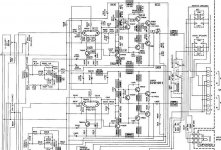
See attached file.
If those were removed, its probable that there's more issues.
However, that has about 38+38 v DC from the power supply sitting atop the heatsinks (check to see), and that feeds to the two large and foul smelling caps currently leaking goo onto the circuit board.
If the little power supply is unplugged from the main circuit board, the rest of the amplifier continues to run except that the bass and treble controls will quit working. EDIT (just like they are now). 😉
However, right back of the volume pot and bass-n-treble pots, you'll notice the only two orange capacitors in a sea of blue capacitors. Those two orange capacitors, probably 4.7uf are nice quality input filter/dc decoupling caps. Hooked to them is 2.2k in series and 100k load. All of these parts are good. The 4.7uf there is especially wonderful if bypassed (paralleled) by 0.01uf to 0.0068uf polyester film caps.
Also, of course, this is the location to desolder, recycle and patch in. . .
I believe that prebuilt Hypex amplifier modules fit that particular voltage. Some are available with the pre-drive (op amp) stage onboard. That's good because the Technics is a passive preamp, with no boost of its own.
Anyway, check the voltage and
Two issues remain. . .
In order to bypass the speaker relay mess, you can remove the two leads, and put them on the opposite (output) side, because the speaker relay is inactive.
However, any new modules do require individual ground lines run directly to the speaker terminals for both left and right and specifically not use the case ground for speaker ground.
Fortunately, the old speaker terminals are awful, an ordinary bit of fiberglass fits the hole, and then hookup is quite simple. 😉
After having disconnected the little power supply from the mainboard (not from the transfo), then you can remove the 10,000uf smelly leaking caps. However, you do need more smoothing than that pair of coin-size ceramic caps. Fortunately, a couple of 63v, 4700uf can attach directly to the power supply-- or you could just hook the transfo right to a nice new power supply.
Since I don't usually make much sense whan I type too much. . . 😉
See attached file.
Attachments
If this is anything close to the old Technics amp I have, it probably uses one of these hybrid ICs (in other words it's not a true IC, but rather a purpose-built device with transistors and resistors on a common substrate). If the IC is fairly large then that's probably what it is.
Something like the STK**** series made by Sanyo.
These are obsolete so might be pretty hard to find. Assuming that's what's actually in there, cause I'm just guessing here.
Something like the STK**** series made by Sanyo.
These are obsolete so might be pretty hard to find. Assuming that's what's actually in there, cause I'm just guessing here.
First production run models like SA5070 are compatible with NEC transistors, all starting with 2S***** And after that point, its over my head. 😉
this one has an IC which has been removed from the shop he took it to.
I will just leave it like the shop recommended (another amp with a volume control which he adjusts) but it doesnt seem like much point keeping the technics just as a source switcher/tuner so maybe its better just to replace if the ICs are not available.
I will just leave it like the shop recommended (another amp with a volume control which he adjusts) but it doesnt seem like much point keeping the technics just as a source switcher/tuner so maybe its better just to replace if the ICs are not available.
Well, it is a beautiful warm passive pre with onboard stereo radio and a nice turntable amp. Its current employment has it providing a nice feature set onto whatever power amp you'd like to connect.
A service manual is too large to send as an attachment here, but I do have the 5370 service manual. Since those are unit built, its probably mostly interchangable. If you'd like to receive it, send me an E-mail. It has a clear replacement parts listing.
EDIT: The right one is about $15 instant download from servicemanuals.com
It is also adapable as a full passive pre so that all but the previous power amp parts (bass-n-treble, headphone jack, speaker selector) controls regain their function.
To make this adapation for passive pre:
1
Remove the plastic rear panel that holds speaker terminals and replace it with a fiberglass panel with 2 RCA jacks.
2
Remove the two power lines that go from the power supply to the mainboard power amp, but leave the ground wire in place. Leave the power supply in place to give the transformer stability.
This will deactivate the two large tank caps.
*The radio and turntable amp will remain functional because they are powered by the secondary windings and the little supply that's over by the headphone jack (the only large blue cap indicates the location of the secondary supply).
3
Locate the only two orange capacitors on the power amp side. That's probably 4.7uf--right up front by the potentiometers. They're great--save them. 😉 Next to them are 2.2k (input in-series) and 100k (load). Remove these three pieces (per channel) and attach the new power amp at this location. That's a signal cable from here to (#1 above) the two new RCA jacks on the back panel.
4
A little compressed air and then some Deoxit in the balance and volume controls, and the old receiver is ready for its new life as a passive preamp with radio and riia.
As you can tell, its not far from passive pre to actually installing a new power amp (Hypex or LM3875) right onto the original heatsinks.
But, sure I'll send you a service manual if you want it. Just send me an email.
- Status
- Not open for further replies.