Hi All: Havent posted in a LoooonG time but need some help. I am building a simple RH84 from Kitic's excellent board but having troubles with a suitable power supply.
Being a poverty-stricken oldster, I cannot afford to eBuy a proper power transformer. Luck hooked me up with an ancient Marconi 224 radio, from which I have salvaged a working transformer and a healthy 5Y4G rectifier. My problem is this:
Transformer has the following outs: 5Vac, 35Vac (heaters are in a string) and 680Vac CT.
Wired up the 5Y4G with C-R-C (150uf, 470r, 33uf, 400V caps) and I get 450Vdc .
This is odd because the Marconi schematic shows the original PS caps are rated at 20uF/300V and 30uF/360V.
Tried a half-wave 1N4007 on one side of the HV out (measures ~340Vac). I was going to create two separate PS circuits each using one half of the 680V CT windings.
Wired this up for one side to test C-R-C-R-C (150uF, 470r, 0.47uF, 470r, 33uF) from this trafo and get 447Vdc!
I can't understand why the output measures so high in either case.
I have modeled this and other configurations on PSuD and it predicts 312Vdc out at 112mA - not even close to what I am measuring.
I think that this whole thing is hinged on the load (both the real and simulated). For PSuD I have guesstimated the load at 5K, but this is probably miles off. I have noty been able to find any infor on the actual load an RH84 presents to its PS. If anyone knows that it would help a really-really lot.
As you all probably know, I need 315V/100mA for the RH84. Can anyone explain a) why the outputs of the two configurations measure 400V+ and b) how I might drop the PS Output without restricting the current too much?
Cheers all
Jess
The absolute maximum capacitor value on the cathode of your 5Y4G is not to exceed 32uF and it should feed a choke before another 32uF capacitor.
340 0 340 will give you about 380v off load through your valve, due to about a 90volt drop in the valve.
Why are you placing a 470n in there, this is not a semiconductor power supply!
You cannot successfully simulate a valve circuit. All valves, even of the same type, are different ... build it and see what really happens. Get your fingers wet and gain experience like us seasoned engineers did.

You need a L-input filter, + a bleeder resistor combined with a full-wave rectifier. With silicon diodes, you should arrive at ~330VDC, which can be tweaked with one or two additional RC cells.
With a tube rectifier, the bleeder can be lighter and RC cells shouldn't be required, for the voltage at least: you may want them to improve the filtering, in which case the bleeding can be even lighter.
In your case, choke input is practically mandatory
With a tube rectifier, the bleeder can be lighter and RC cells shouldn't be required, for the voltage at least: you may want them to improve the filtering, in which case the bleeding can be even lighter.
In your case, choke input is practically mandatory
You need to load the oiutput before your can know what the actual DC is.
I was using a 5Y4G with 320-0-320 HT transformer which gavae about 330v.
I replaced this with a pair of BY255 1300v diodes and have 350v after a 50mh choke filter.
I was using a 5Y4G with 320-0-320 HT transformer which gavae about 330v.
I replaced this with a pair of BY255 1300v diodes and have 350v after a 50mh choke filter.
That.
Or give it what it expects.
Forget silicon diodes and creating two half wave supplies, etc ..
Wire it "full wave" like God and Marconi intended 😄, use your tube rectifier, get original value caps, load it with your RH84 which will be in the ballpark of what's expected, all will be well.
Post RH84 schematic or project link here.
You are the asker, you supply the data 😄
Thank you all for your valuable input. I will stick to the tube domain and foreswear that solid-state stuff! Seems like I will need to go searching for parts. I got the whole radio that the trafo came from - the schematic shows a C-L-C config with 20uF/360V, a choke labeled "L.S.FIELD and a 10uF/300V. From this I take it that they were using the field coil of the loudspeaker for a PS choke. Does this sound right?
Yes.
Since they had to "waste" power anyway to feed the field coil, why not make it do double duty? 😄
Which also drops some +V voltage.
That's why you measure today more than expected.
You can add a choke if you find one, or a proper value resistor, but final value will come after RH84 is working properly
in its place.
Hello Jess:
Welcome back to the forum and tube audio.
If you go with a L-C-R-C .

You will be able to drop a lot of voltage and get a nice stable B+. The C1, C2 do not need to be large, in the 22uf range is fine. The L is doing the heavy lifting in this design. The R is used to fine tune the final B+
You can approx the load with a 3K ~ (312V/ 112ma) 30W ~ (.112A x 312V) resistor or a string that adds to about that. It will get hot but allow you the get the B+ in the ball park.
The unloaded B+ is always way different from the loaded. Because the transformer has inherent poor regulation. It is flapping in the wind as they say.
I hope this helps
Give me a call, maybe I can help?
Welcome back to the forum and tube audio.
If you go with a L-C-R-C .
You will be able to drop a lot of voltage and get a nice stable B+. The C1, C2 do not need to be large, in the 22uf range is fine. The L is doing the heavy lifting in this design. The R is used to fine tune the final B+
You can approx the load with a 3K ~ (312V/ 112ma) 30W ~ (.112A x 312V) resistor or a string that adds to about that. It will get hot but allow you the get the B+ in the ball park.
The unloaded B+ is always way different from the loaded. Because the transformer has inherent poor regulation. It is flapping in the wind as they say.
I hope this helps
Give me a call, maybe I can help?
Last edited:
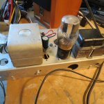
So... I thought you guys would get a giggle out of this. Here I am whimpering about being too broke to afford a 5H choke (shipping is 2X purchase cost).
Then it struck me - the Marconi radio I salvaged the PS parts from used the coil of the speaker as a choke in the original design so why can't I do the same.
I got out the mini grinder and cut the coil away from the old speaker frame, mounted it on the PS chassis and connected the circuit through the coil.
Guess what... it works! What's more, the EL84 amp sounds great and there is NO HUM - not very little hum, NO HUM at all.
Anyway, thanks for all the suggestions and ideas. All good now. 😊
Attachments

N stead of a magnet on the speaker they killed two birds with one stone…or coil. The power supply choke served as an electromagnet for the speaker. Magnets were expensive and they needed a choke for the PS.
Hi, plan on building an RH84 except I'd like to use Solid state rectification to save some money since most of the parts will be scavenged.
This poses two issues: 1) Higher voltage and 2)tubes get power instantly before heaters warm up.
My novice brain came up with two workarounds but I'm looking for feedback on them.
1) Compensate the voltage drop created by the tube rectifier by using a voltage divider and get the B+ i need.
2) instead of having 1 On/off switch on the primary, would it make sense to put a switch after the rectified b+? that way initially tubes only get 6.3v to the heaters and after say 20 seconds i turn on the b+ switch to the rest of the circuit. Is it dumb? Anything I'm missing?
Surely there is a more serious approach to something like that to delay itautomatically but I'm clueless and I don't know what I'm doing.
You will have a problem finding a switch for typical B+ voltages as this was a thought I had until I couldn't find a switch.
For switching high voltage you could use a vacuum relay. A bit more expensive, but very reliable.
Regards, Gerrit
Regards, Gerrit
- Home
- Amplifiers
- Power Supplies
- Need help with HV power supply