Hey guys, Thanks in advance to all the guru's for looking and hopefully helping out. I just received a Kicker 1200.1 and it doesn't have any sound output. Yes, I've been researching and testing to no prevail for the past 5 days before joining and posting. Perry, you seem like the go to guy on these amps. I hope you can help.
So I powered it up, no protect lights powers up fine but no output. it looks as though the relay on the output side isn't latching/ or turning on? I believe it is stuck in that position to prevent a bad signal output? Nothing in this amp is burnt, blown or has any signs that it is bad... I check the rail voltage, the TL484C and from all the other threads I've read they are fine.
So, here I am hoping for some guidance. I've fixed a lot of minor amp issues, like rca's, burnt traces, etc... but never been this deep into one before. Any help would be greatly appreciated. Thanks again.
With the black meter probe on the negative speaker terminal. is there any significant DC Voltage on either terminal of either of the output filter inductors as the amp is powered up?
If you drive a strong signal into the amp, do you read any AC voltage on the same point?
Do this with all FETs clamped tightly to the heatsink.
You stated that the rail voltage was OK. What was the rail voltage?
If you drive a strong signal into the amp, do you read any AC voltage on the same point?
Do this with all FETs clamped tightly to the heatsink.
You stated that the rail voltage was OK. What was the rail voltage?
Hello Perry, Sorry for the delay...
Hopefully, I tested the right components. Like I said I've never dove into an amp before other than loose RCA's and traces. But here's what I got when I tested component:
L107
+2.3v AC was the highest reading on this component +1.7v was consistent with 2v preouts
On the other 2:
L105 & L106
+1.7v on the inside pins and the outside pins it seemed as tho my meter didn't have a high enough setting. Now when i removed the probe from the pin I would get weird readings as high as 777v Ac but every time I stuck the probe on and off I would get different readings. It's just a cheap CEN-TECH 98025, I should have brought my good one from work home.
The readings I got on the rail with a input of 13.7v DC from my power supply were:
13.3v and also 68.4v DC
Thanks again for your help and have a great Holiday.
Ok found another meter, it's not the bluepoint but it's not a cen-tech either. It's a craftsman. I believe it's reading tho... I have the gain set at around 3/4 on the amp and now I'm reading up to 120's AC on the L105 & L106 outside pins and around half or less on the inside pins. I am also getting around the same 50-60 volts ac on the L107 pins. they all fluctuate with the volume up and down.
What about the DC voltage?
If you set the meter to AC volts and touch the probes across the 12v power supply terminals, what does it read?
If you set the meter to AC volts and touch the probes across the 12v power supply terminals, what does it read?
There is about 70-80 volts DC on and off, keeps flashing my meter like it needs a higher setting?
I have it on 200 DC setting...
If i put the leads across the power supply it reads 29.6 volts AC.
I have it on 200 DC setting...
If i put the leads across the power supply it reads 29.6 volts AC.
This meter isn't likely to be reliable for critical measurements, especially for AC since the AC circuit didn't read 0v when touched to the DC power supply.
The most common fault in these amps when you have DC that's causing the amp to shut down is a faulty LM361 (U14).
Measure the DC voltage on pins 9 and 11 of U14. Place the black probe on the negative speaker terminal. Post the voltage on those two terminals.
The most common fault in these amps when you have DC that's causing the amp to shut down is a faulty LM361 (U14).
Measure the DC voltage on pins 9 and 11 of U14. Place the black probe on the negative speaker terminal. Post the voltage on those two terminals.
LM361
Pin 9: -0.05
Pin 11: 0.48
Also it looks as tho the LM361 might have been replaced because the top is all scratched like someone tried to erase the numbers. U12 also has been scratched off.
Pin 9: -0.05
Pin 11: 0.48
Also it looks as tho the LM361 might have been replaced because the top is all scratched like someone tried to erase the numbers. U12 also has been scratched off.
The amp manufacturer defaces the ICs.
Those are inconclusive.
Post the DC voltage on all pins of U14. Copy and paste the following into your reply.
Pin 1:
Pin 2:
Pin 3:
Pin 4:
Pin 5:
Pin 6:
Pin 7:
Pin 8:
Pin 9:
Pin 10:
Pin 11:
Pin 12:
Pin 13:
Pin 14:
Those are inconclusive.
Post the DC voltage on all pins of U14. Copy and paste the following into your reply.
Pin 1:
Pin 2:
Pin 3:
Pin 4:
Pin 5:
Pin 6:
Pin 7:
Pin 8:
Pin 9:
Pin 10:
Pin 11:
Pin 12:
Pin 13:
Pin 14:
Pin 1: 11.75
Pin 2: 0.00
Pin 3: -0.01
Pin 4: -0.03
Pin 5: 0.00
Pin 6: -11.91
Pin 7: 0.00
Pin 8: 2.90
Pin 9: -0.07
Pin 10: -1.85
Pin 11: 0.49
Pin 12: 0.00
Pin 13: 2.90
Pin 14: 2.90
Pin 2: 0.00
Pin 3: -0.01
Pin 4: -0.03
Pin 5: 0.00
Pin 6: -11.91
Pin 7: 0.00
Pin 8: 2.90
Pin 9: -0.07
Pin 10: -1.85
Pin 11: 0.49
Pin 12: 0.00
Pin 13: 2.90
Pin 14: 2.90
I don't see anything significantly wrong there.
With your meter set to ohms, confirm that you read 0 ohms between the point indicated by the arrow and any terminal of the outer output filter inductors. If so, when the amp on, measure the DC voltage on the point indicated by the arrow, black probe on the negative speaker terminal.
With your meter set to ohms, confirm that you read 0 ohms between the point indicated by the arrow and any terminal of the outer output filter inductors. If so, when the amp on, measure the DC voltage on the point indicated by the arrow, black probe on the negative speaker terminal.
Attachments
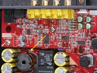
Drive a strong audio signal into the amplifier and check for AC voltage on that point. The AC voltage should correspond to the level of audio driven into the amp.
- Status
- Not open for further replies.
- Home
- General Interest
- Car Audio
- Need Help with another Kicker 04kx1200.1