It's a very high frequency oscillation, so it seems to be mosfet related.
Underbiasing of one of the devices might be a cause - I certainly seen rampant oscillation in an under-biased lateral output stage, and conditional stability IIRC.
Bob Cordell recommends snubbers for the gates I believe, something like 39pF+100R.
My other thought is that emitter/source resistor inductance is more critical for MOSFETs which are fast - are they wire-wound?
If so try metal-oxide.
Last edited:
I forgot to say, board layout may be an issue. Also make sure the PCB is clean and free of any residues, solder flux etc. Use alcohol and a cotton bud/toothbrush to clean up the area.
Another update:
Kramtweeter, yes, I agree that the P-channel side is probably where the problem lies. I am going to try increasing the gate stopper resistance. The PCB is in good condition.
jxdking, I know that is a problem, but I do not want to compromise a commercially active design.
Mark Tillotson, I read about gate snubbers, but this topology works just fine on another sample of this amplifier that I did not blow up, so I probably won’t try that. Inductance of the source resistors is an interesting thought. I only replaced the source resistors on the N-channel side, the P-channel side are original to the design, so they are completely different. I will look into that a bit.
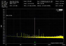
I increased the resistance of the gate stopper resistors to 1000 ohms on Q3 and Q4, the P-channel devices.
That did stop the oscillation bursts. To maintain a circuit balance, the gate stopper resistors on Q1 and Q2 were also increased to 1000 ohms.
The large difference in bias between Q1 and Q2 still exists, but as stated previously, my best guess is that it is a function of the specific devices on this PCB.
The distortion spectrum now looks much better, see attachment.
So, this amplifier is probably as fixed as it is going to get.
Thanks to everyone that offered advice.
Cheers,
ceulrich
Kramtweeter, yes, I agree that the P-channel side is probably where the problem lies. I am going to try increasing the gate stopper resistance. The PCB is in good condition.
jxdking, I know that is a problem, but I do not want to compromise a commercially active design.
Mark Tillotson, I read about gate snubbers, but this topology works just fine on another sample of this amplifier that I did not blow up, so I probably won’t try that. Inductance of the source resistors is an interesting thought. I only replaced the source resistors on the N-channel side, the P-channel side are original to the design, so they are completely different. I will look into that a bit.
I increased the resistance of the gate stopper resistors to 1000 ohms on Q3 and Q4, the P-channel devices.
That did stop the oscillation bursts. To maintain a circuit balance, the gate stopper resistors on Q1 and Q2 were also increased to 1000 ohms.
The large difference in bias between Q1 and Q2 still exists, but as stated previously, my best guess is that it is a function of the specific devices on this PCB.
The distortion spectrum now looks much better, see attachment.
So, this amplifier is probably as fixed as it is going to get.
Thanks to everyone that offered advice.
Cheers,
ceulrich
Attachments
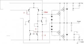
Hi, I think your oscillation comes from input stage, to high gain in VAS and non adequate Miller compensation. Try increase Cdom capacitor. Second put same capacitor on position 2 or position3, or put compensation capacitor of 100-330pf on position 3.