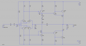
Hello , I recently build this amplifier.
Power rails are +22 0 -22. Power output I wanted to be 15v rms in 6 ohm
I only get 9v rms clean, after that 10v sound distorted a bit , 11v and till max output are distorded ( 10thd + or so , by ear ) Power Supply is not the problem ( even at 15.7v output with distortion, from 22v i drop to 20.7 , soo it's enough for a clean 15v output ). May the problem be Q5 Q6 quissance current to low ?.
Output stage quiss current is 80mA.
Q9 Q7 are togheter with D1 D2 on a " small " 2cm by 0.5cm piece of aluminium ( with mica isolators ) Quissance current is stable , won't run away.
Should I change R9 R10 , may that fix the problem ?
or should I change Q5 Q6 to BD140-BD139 that can take more quiss current.
Thank you.
Also , input signal is not the problem why it distorts.
Attachments
Should I change R9 R10 , may that fix the problem ?
or should I change Q5 Q6 to BD140-BD139 that can take more quiss current.
Thank you.
You are addressing the next logical step with these questions. Have you verified that the Vas stage is swinging full voltage, with relatively symmetrical clipping? If not, address that. If so, then look at the output.
It can be hard to get that last couple volts of swing. This is exacerbated by low voltage rails.
Hi,
You calculate the voltages in a wrong way.
According to your schematic, you will loose roughly 4V of swing at each rail.
That means the maximum swing is 18Vp = 22V - 4V.
Vrms = Vp / sqr(2) = 12.6V rms (roughly).
That's the maximum RMS swing you can get if your rails do not sag.
But they do sag, so the real swing is even smaller - as you can see in practice.
Cheers,
Valery
Amp looks fine and you should have some 15/18W RMS into 6 ohms.
By ear?
Ear is the most imprecise "measuring instrument".
Feed the amp 1kHz sinewave , slowly rise volume until it clips, then lower slightly until it just stops.
Then measure V RMS and do the Math.
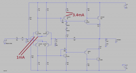
Maybe 3.4mA available at the Vas stage is too tight, if transistor pair combined Hfe is on the lower side, but first do the test suggested above.
HOW are you measuring power out?I only get 9v rms clean, after that 10v sound distorted a bit , 11v and till max output are distorded ( 10thd + or so , by ear )
By ear?
Ear is the most imprecise "measuring instrument".
Feed the amp 1kHz sinewave , slowly rise volume until it clips, then lower slightly until it just stops.
Then measure V RMS and do the Math.
Maybe 3.4mA available at the Vas stage is too tight, if transistor pair combined Hfe is on the lower side, but first do the test suggested above.
So, calculating the other way round, assuming you are looking for 15V RMS, assuming around 4V of loss in VAS/OPS and some 1.7V for sagging, you may want to have your rails at +/-27V as a minimum. Practically, allowing some headroom for lower distortion at 15V RMS, I would go for +/-30...32V rails.
ok, so for 35v 0 35v as i have another transformer (35-0-35 dc )
Should i change resistor values, in LTspice i get around 8mA fro vas is it to much ?.
Thank you.
8mA is going to be fine - use some small snap-on heatsinks for Q5, Q6 for better VAS idle current stability.
ok , than you , I will try with 35-0-35 v transformer , with the same values , measure vas current , and try 1khz test to see now what power I get.
Yep. If Q5, Q6 will run too hot - just slightly increase the values of R15, R16 - some 24K or 27K are going to be fine.
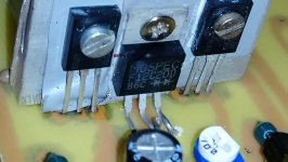
I have mounted D1/D2 on a small heatsink with the drivers BD139/140.
As soon as the drivers get warm , quiss current drops. ( This is ok for not making output transistors go in thermal runaway right? ). But it drops pretty much, from 90mA to around 20mA. I've set it on 70mA while the amp was warm, Now with the amp off for a half hour , plug it in I have 190mA quiss current , that starts to drop slowly, as I play a song on low volume , the quiss current goes to 70-80mA . Should I let it like this ?
Should I set the quiss current ( JUST TO TEST ) to let's say 300mA and let it without signal to see if it drops , and how much ?. Thanks again.
That can basically mean 2 things:
1) your drivers get too warm;
2) your bias tracking is too sensitive, so that it over-regulates.
In case of (1), increase R12, R13 up to, say, 150R and see if the drivers get cooler and the whole thing behaves in a more stable way.
If it still over-regulates, try to mount on the driver's heatsink only one diode (the second one just leave on PCB.
Cheers,
Valery
You should replace the diode bias chain with a transistor attached to the same heatsink as the BD139/BD140. The transistor needs a variable resistor in the base side to be able to adjust the current. Diodes+resistor can change with the current (the resistor needs to be changed anyway for a higher current).
For 8mA bias I would suggest a BD139 transistor instead of the diodes; collector to base resistor 1k, base to emitter resistor 1k potentiometer plus 680 ohms, and you may want a small capacitor (0.1u) across it.
For 8mA bias I would suggest a BD139 transistor instead of the diodes; collector to base resistor 1k, base to emitter resistor 1k potentiometer plus 680 ohms, and you may want a small capacitor (0.1u) across it.
Last edited:
- Status
- This old topic is closed. If you want to reopen this topic, contact a moderator using the "Report Post" button.
- Home
- Amplifiers
- Solid State
- Need help with an Amplifier