Max is thinking glue. My meter has a setting to test capacitors. Should I test them first? I don't think there's a consensus either way that they were leaking. If I should test them, do I need to remove them from the board, or can I leave them in place? I'm not disagreeing, or anything. Just trying to learn.
Interesting. If the resistor reads as you say out of circuit then its definitely faulty. The cap, well I would be surprised if there were a problem with it tbh. The circuit shows the base and collector of the transistors (next to the cap) as shorted  That's a definite typo.
I would just fit any 100 ohm in there and see what other issues show (if any). You may find the bias current much higher when a 100 ohm is fitted so beware and check and reset it immediately.
o
Very strange that resistor... as a one off fault anyway...
That's a definite typo.I would just fit any 100 ohm in there and see what other issues show (if any). You may find the bias current much higher when a 100 ohm is fitted so beware and check and reset it immediately.
o
Very strange that resistor... as a one off fault anyway...
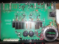
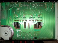
Attachments
There certainly could be other issues. I'm kind of running blind at this. I'll see if crappy Shack has anything that will work. I'm going to have to replace that cap, due to operator error. If that solves it, I'll order the good parts. Rotel certainly didn't skimp on these components. They weren't that easy to find.
You mean you've melted the cap with the soldering iron
The resistor can be any 100 ohm 0.25 or 0.5 watt. The cap can be any type as a test, even a ceramic will do to get it all working.
Its a strange problem because DC faults usually give an output voltage that is hard up to the rails... and this isn't... which may be a good sign and that its just the huge imbalance in currents that is causing an uncorrectable offset.
Worst case (and you need to check this because I see you mention almost no audio output in the first post) is that the output stage is zapped and the 0.22 ohms are open circuit together with failure of the output transistors. If I'm honest I would probably have said the amp would still work with just the resistor at 140 ohms... hmmm.
Switch off and have a measure at those four 0.22 ohms.
Worse than that. I accidentally pulled the lead out of one side. I measured resistance across all the transistors in circuit when I was going through it. I know that won't give me an absolute reading, but I figured I could look for differences between the good side & bad. The differences were negligible, but that method is what turned up the resistor.
I measured resistance across all the transistors in circuit when I was going through it. I know that won't give me an absolute reading, but I figured I could look for differences between the good side & bad. The differences were negligible, but that method is what turned up the resistor.The 0.22 resistors are all intact. Unfortunately, I can't get an accurate reading with my meter due to lack of decimal places. It only reads 1 place. All the resistors read 0.1 or 0.2, so at least no open circuit. Crappy shack had good enough resistors. Caps were a different story. I bought a multi pack that had 7's & 15's which I can parallel up to 22.
Just got everything back together. No change.
So we do some basic measurements with it switched on. I would suggest not having speakers attached for this.
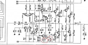
Measure and record these results. (The circuit I have is a bit blurry for quoting reference numbers). Also I assume the DC supplies are correct at around -/+50 volts.
1) The actual DC offset measured across the speaker terminal.
2) The voltage across the two pairs of series connected diodes. You should see around 1.3 volts across each pair.
3) The voltage across both of the 100 ohms (R622 and R624. How does that compare with the good channel ?
4) Measuring from ground, the voltage on the cap you replaced and also on the similar 220pf cap at the top. There should be around the 1.6 volts shown in the circuit. The bottom cap reading should be minus 1.6 ish, not plus 1.6 as shown. (There are quite a few anomalies and errors on the diagram)
I ordered a 10 pack of the proper fuses today. Then I set up a workstation in my spare bedroom & went to work. I powered it up & things had changed. Instead of getting a 0.4v offset, I got a 47v offset. I've been reading a lot over the past couple days & this made me think that a transistor went bad & powering it up for the first time in 12+ years had pushed it over the edge. The cap at c608 had also bulged noticeably. I pulled the cap & it measured 85ufd instead of the 100 it's rated for. Then I pulled all of the output transistors on that side. Sure enough, q634 & q628 are dead short. I'm planning to source exact replacements for all of those, plus the cap & resistor I found the other day. I don't know if I should replace any other components while I'm at it. I want to make as few orders as possible, since I'm sure the shipping will be at least as much as the parts. If you have any suggestions on other components to check, let me know. I can't power it up at this point, but I'm back up to speed on circuit board soldering, so I can always pull individual components. Thanks again for all the help.
The secret to rebuilding this is to take it slowly... use a bulb tester (that's a must) and follow a definite plan. It would be usual to replace all the outputs with similar devices as well as the drivers and pre drivers. Beware buying semiconductors on ebay, too many fake devices around. You need to check all the low value resistors around the output stage.
The amp will power up and work with just one pair of output devices fitted so you can pull the zapped ones and try it if you want but you must use a bulb tester to stop damage if any other problems exist.
The amp will power up and work with just one pair of output devices fitted so you can pull the zapped ones and try it if you want but you must use a bulb tester to stop damage if any other problems exist.
....he cap at c608 had also bulged noticeably. I pulled the cap & it measured 85ufd instead of the 100 it's rated for......
Generally electrolytic caps bulge when they fail. Noticeably when the supply voltage on it is higher than it's rated voltage. Could also happen with old caps. That 85uF measurement for 100uF doesn't mean too much. Most electrolytic caps can vary 20% around it's rated value.
Replace the caps with similar voltage rating or a bit higher. This doesn't appear to be the main supply cap and so I wonder why it failed. Maybe because the other components failed ? I don't have a circuit diagram with me.
The 22pf capacitor appears to be an LCR Components FSC 160V 22PF+/-1PF. The 100 ohm resistor appears to be a Vishay CCF07100RGKE36. The pics, appearance, markings & ratings are identical to what's in the amp. I found them on Newark.com, so I'm thinking it's possible that they're the parts house that Rotel uses. I'll check them for the other components & hopefully be able to order everything from one source. Should I replace all the output transistors, or just the bad ones, to start. The other ones all test right, with no leakage on the meter. As a precaution, I'm going to replace the ceramic resistors, since i can't really measure them. I'm planning on pulling a leg on each resistor in the power stage & testing them to make sure they are all in spec. I'm also going to pull & test the other electrolytic caps in the power stage. The power supply is giving 50.2V to each rail, so it would seem that that's ok. As I'm brand new to all of this, I'm unfamiliar with what a bulb tester is. Could you describe or link one & give a brief explanation on how to use it? Thanks.
I just uploaded the factory service manual to my dropbox. It's hard to read, but usable. Here's the link. https://www.dropbox.com/s/fa746mkvq20y2ab/rotel_ra-970bx_sch_[ET].pdf
The bulb tester is a 100 watt (or near offer) mains filament bulb wired in series with the mains supply to the amp to limit current. If there is a problem the bulb will light rather than output devices going up in smoke.
Have a read at these to get an idea what is involved. All amps follow the same basic pattern for fault finding.
http://www.diyaudio.com/forums/solid-state/251459-marantz-pm-66se-ki-bin-repair.html
http://www.diyaudio.com/forums/soli...-1500-sounds-weird-youtube-link-included.html
I wouldn't worry over sourcing "identical" parts... that makes things difficult. Resistors and caps from any reputable supplier will be fine. Transistors... I would go with "modern" replacements every time tbh.
- Status
- This old topic is closed. If you want to reopen this topic, contact a moderator using the "Report Post" button.
- Home
- Amplifiers
- Solid State
- Need help with a Rotel RA-970BX