Need help with a projet involving solar cells and SLAs
Basically it's a battery feed power supply with a dual recharging option.
The output of the power supply has to be 13.2V capable of at least 3A peak draw. The source however beign an SLA, actually 2 SLAs, which will vary in voltage from 13.8V (15.2V while fast charging) fully charged down to 10.5V almost fully discharged. So I'll need some sort of DC-DC converter.
The SLAs will be charged by a solar panel with 16V 1A output, actually 32 0.5V 1000mA individual cells as the primary option. This could be done by simply float charging the SLAs but since voltage from the solar cells may drop with the amount of sunlight, maybe a better option would be to have another DC-DC converter feed a proper charger circuit, eg based on a UC3906 or Maxim712, to ensure that every single mA available in the solar cells is used to recharging the SLAs.
With the latter option it is also a simple matter of finding/building a power supply to feed the charger when in contact with a power grid. I would much prefer a SMPS for this.
Being a total eletronics design n00b, I have the following question for you to ponder:
1) Anyone know of a DC-DC converter design that accepts 10.5V to 15.2V inputs and outputs 13.2V 3A peak?
2) Anyone know of a DC-DC converter design that accepts from 16V down to as low as possible and outputs roughly 16V 5A peak (1A peak with solar cells)?
3) I found several SLA battery charger designs on the net, anyone has a favorite (has to be switch mode)?
4) Finally I need a design for or a ready-made SMPS that accepts 240v AC and outputs around 16V (to be feed to the recharger), anyone know any good designs/makers? (I'd probably prefer a ready-made one as fiddling with high and potentially lethal voltages isn't exactly my cup of tea.)
5) Is it safe to parallel 2 SLAs or should I have some sort of switching circuitry that would charge on one battery while the other is under load, and how would you go about designing such a thing?
6) Does this all sound crazy? Am I missing something important? Comments?
Btw, as a final note, I should mention that battery life is paramount so high effeciency circuits is much preferable.
Thanks in advance.
Johnny
Just for my basic understanding: An SLA being some sort of battery?
1) I recommend using a SEPIC topology. I dont believe you need isolation, and in its principle sepic is easy to understand. Last but not least, it can do both step up, and step down. Do some goole-ing on the topic to learn more.
2) working voltages up to 16V is probably not nescesary, as you will find that Solar voltage will drop significantly when you draw power. You might just get away without converter, having the batteries dictate the voltage delivered by the solar cells. Keep in mind that solar cells act like current sources, not like voltage sources. Find out what the IV curve is for your panel, and if your Maximum Power Point is around 13V, presto! You won't have optimum efficiency from your panels under all circumstances, but its an easy way home. Else, you should consider boost or another sepic.
3) no favorites 🙂 I think you can get away with a two step charge process
4) You should search the net for any wall adaptor. Maybe you can get lucky with an old laptop supply, or any other adjustable PSU. Should you have to do it yourself, I suggest you use Flyback Topology, as it will offer you isolation in the transformer. search for TOPswitch IC's that can help you design your PSU easy. Only catch will be the transformer, but i'm sure you can find help on that as well.
5) provided that SLA's are wht I think they are, I think thats fine. be sure that your converters are current limited.
6) Maybe some block schematic to help clear things up...
Good luck!
Bakmeel
for 2)...
since your open clamp voltage for the Solar cells is probably 16V, and if you choose to go without a charger, you will need an End-Of Charge switch between Solar Cells and Batteries to prevent overcharging the battery.
Bakmeel
since your open clamp voltage for the Solar cells is probably 16V, and if you choose to go without a charger, you will need an End-Of Charge switch between Solar Cells and Batteries to prevent overcharging the battery.
Bakmeel
Thanks for the information.
SLAs are Sealed Lead Acid batteries, or gel-cells as they are also know as.
After reading a lot about SEPICs and flybacks, along with whole slew of other stuff, it struck me that I probably can make do with a lot less sophisticated design. I thank you for pointing me in that direction though as I could most certainly use it in a later design.
Basically the output which is to feed 2 T-Amps doesn't really need a regulated output nor do they need a minimum voltage as they will cut off at roughly 9.5V by the internal protection circuit. I really only need to limit the output voltage to 13.2V, and that could be easily done by 6 diodes.
A schottky in series between the plus of the solar panel to the plus of the SLAs, 4 3.6V 5W zeners in series connected in parallel with the SLAs from their plus to ground, and finally a series diode from the plus of the SLAs to the plusses of the Amps, naturally with a big cap across the rails.
This should keep dissipation the lowest possible as the voltage drop from the solar cells is only 0.2V. And keep a steady float charge voltage of 13.8V while remaining within 80% of the zeners capacity. And finally would drop the maximum output voltage to 13.2V through the series diode.
All I need now is a common switch to switch the SLAs between online solar charged mode and offline fast charge mode, for which I've found a suitable design. Hell, I might even be able to design an automatic relay circuit that would switch into offline fast charge mode when power was connected.
I hope that this is correct, please correct me if I'm wrong.
Thanks in advance
Johnny
32 & 33 solar modules are generally considered "self-regulating". They are intended for direct connection to the battery, and in general will not overcharge the battery... much depends on your operating temperatures.
Efforts to maximize charging efficiency by boosting or bucking the solar panel's voltage are generally not cost effective for small systems... under 1000 Watts. There are exceptions to this of course, particularly where AC power is being generated. Systems where space is limited can also benefit power conversion (google MPPT... Maximum Power Point Tracking). You can get 15% more power, but on a small scale 15% more solar panel is usually less expensive.
What Amp-Hour capacity are you planning?
Yes, you can parallel 2 batteries... no problem at all. See the attached diagram for wiring methods... it DOES matter.
Your output can be stabilized with a DC to DC convertor. Many sources for these. I can recommend many but I don't know what you have available.
Purpose-built battery chargers can be problematic... usually they are very noisy. So... charging while using the load can cause problems. Power supplies can make good, quiet chargers, but they MUST have an important feature, RECTANGULAR CURRENT LIMITING or CONSTANT CURRENT LIMITING. An RKW 15-10K from Kepco is an excellent choice.
http://www.kepcopower.com/rkwo.htm
The key to long battery life is avoiding deep discharge. At light loads your battery should never be discharged below 12.0 - 12.2 Volts.
Attachments

Does that recommended wiring scheme solve non equal load issues when it comes to charging? I've seen the same scheme recommended for psu caps in // and it makes alot of sense to use it.
I'm think the real high end way would be two sets of SLA's, whereby you can silently swap from in use to charging automagically, I guess the purpose of that would be to keep playing at full power and not risking hearing the supply being charged. Is it practical though?
I'm think the real high end way would be two sets of SLA's, whereby you can silently swap from in use to charging automagically, I guess the purpose of that would be to keep playing at full power and not risking hearing the supply being charged. Is it practical though?
Yup,
In fact, I made that crappy drawing for a cap discussion. Each cap, OR battery see an equivalent resistance and inductance looking out.
I build inverters (100kW ClassD if you will - 😉), and this type of wiring is essential. You can basically melt caps (and batteries) if wired wrong. It all makes sense when you compare the the ESL & ESR of the caps to the interconnecting wires.
I think a single set of batteries with an RF trap betwen the batteries and the load would be just fine... and cheaper.
😉
I dunno, could such a beast not also help by keeping a more stable supply, less variation under load that is, since you can set whenever they switch over. Not to mention the extra juice could add to run time if going full solar. Kind of have a semi controlled sag rate based on available charge. Then we can say it's novel and charge 10X the price.
So far this hasn't sounded like cost is a big factor.
'bout the wiring, I"ll have to try and see how that applies to 4 pole caps, could be worth it, and thanks for sharing that.
Cheers
So far this hasn't sounded like cost is a big factor.
'bout the wiring, I"ll have to try and see how that applies to 4 pole caps, could be worth it, and thanks for sharing that.
Cheers
Depending on the size of his batteries, sag should not be a problem... SLA's pretty damn stiff as far as that goes.
The Zee wiring is a fine point with caps in typical applications. In app's where the caps are highly stressed (full rms currents), it is essential though. I don't allways do it. I sometimes apply the same techniques to paralleled FETs & IGBTs... mostly for balancing stray inductance.
Batteries are a different matter... small changes in voltage translate to large changes in (dis)charge currents etc...
OH... and BTW you don't need to disconnect the solar panel when using the charger. You WILL want a diode in series with the charger to prevent discharging the batteries through the charger's internal reisitors though.
I sometimes apply the same techniques to paralleled FETs & IGBTs... mostly for balancing stray inductance.
Hhmmmm.. nice 🙂
Yeah... that trick never really occured to me until I blew a Powerex IGBT module to smitherines... 1200 Volt / 600 Amp jobbie. Once we cleaned away the ektoplasm you could see the Zee wiring of the individual chips...
🙂
🙂
poobah said:Depending on the size of his batteries, sag should not be a problem... SLA's pretty damn stiff as far as that goes.
OH... and BTW you don't need to disconnect the solar panel when using the charger. You WILL want a diode in series with the charger to prevent discharging the batteries through the charger's internal reisitors though.
My SLAs are two standard Panasonic 12V 7Ah types mostly because they're dirt cheap here. Around half the price of either a 4Ah or a 9Ah.
Strangely enough I have intuitively wired my SLAs in the Zee connetion you suggest. It just seemed logical to me.
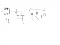
Could I just wire it as shown below? It's schottkys all the diode shown except the regulating zener. And can I even use a zener here? It's my understanding that it dissipates only surplus voltage above the zener point but I'm not sure that totally correct.
Sorry for the lousy drawing. It's free hand *shrug*
Thanks for the advice.
Johnny
Attachments
If it's only dissipating surplus, it's not regulating anything. It's really not a good idea. Use enough capacitance like you normally would anyway, and it will absorbe recirculating current nicely.
What of the possibility of removing that third schottky so that any pumping can help charge the batteries?
What of the possibility of removing that third schottky so that any pumping can help charge the batteries?
classd4sure said:If it's only dissipating surplus, it's not regulating anything. It's really not a good idea. Use enough capacitance like you normally would anyway, and it will absorbe recirculating current nicely.
Yes, but the output needs to be 13.2V maximum with no limit to minimum voltage. The solar cells/SLAs/charger is driving a T-amp which only takes up to 13.2V supply voltage. The idea was to ensure that only 13.2V was outputted by using 4 3.3V 5W zener in series. You're saying that this won't work?
I want minimum voltage loss so probably a shunt regulator then if the above doesn't work?
With regards to you edited suggestion, I suppose I could move the cap to before the schottky and have the same effect?
Aha...
Your Solar Current is 1 amp and your batteries are 7 Amp-Hour...
You will need some charge limiting after all...
Hang on... I'll give you a circuit...
😉
Your Solar Current is 1 amp and your batteries are 7 Amp-Hour...
You will need some charge limiting after all...
Hang on... I'll give you a circuit...
😉
Saturnus said:
Yes, but the output needs to be 13.2V maximum with no limit to minimum voltage. The solar cells/SLAs/charger is driving a T-amp which only takes up to 13.2V supply voltage. The idea was to ensure that only 13.2V was outputted by using 4 3.3V 5W zener in series. You're saying that this won't work?
I want minimum voltage loss so probably a shunt regulator then if the above doesn't work?
With regards to you edited suggestion, I suppose I could move the cap to before the schottky and have the same effect?
I like the shunt regulation alot better of course, but yah that could work I'm guessing. (Haven't done the math tho).
How about a high power TVS as an option to series'd zeners?
I don't think you'd want to move the caps to before the diodes, then the zener would have to drop the pumping current, and you want the caps right at the rails of the amps anyway.
Don't mean to complicate things BTW, but it's always fun to explore options, poobah will keep me straight 🙂
When I said a total electronics design n00b I weren't kidding. So when you off-handedly wrote "calculate everything", I had no idea where to even start looking for information that would enable me to do that.
A few hours on the internet later, I think I'll take a stab at it though.
Firstly, let me see if I get this circuit correctly in it base function. It's basically a transistor assisted shunt regulator, right?
If that's the case then I think the R(collector) should be a 10ohm 10watt type.
The R(ref1) and R(ref2) sets the V(ref) for the shunt, so with an V(input) of 16V and a wanted V(ref) of 14V then R(ref2) should 7 times larger than R(ref1). For convinience let's set it those at 1Kohm and 6.8Kohm respectively. I(ref) for the shunt regulator would then be 8mA which is within the acceptable range.
I'm a little at a loss as for what R(emiter) should be as it would also depend on the used BJT but a stab in the dark could be any value from 1Kohm to 10Kohm, based on assuming it's supposed to be R(collector)*DC gain.
Hope I'm at least partly right. *fingers crossed*
EDIT: I should note that I'm a woodworker by profession and didn't go further than high school, so this tech stuff is really new to me. I have though been programming CNC machinery for a number of years, so the math is somewhat familiar at least.
You're doing pretty damn good!
The collector resistor should ideally be 7 ohm (use 7.5), this unloads as much heat as possible from the transistor (1/2 the total voltage).
Rbase can be in the range of 1 to 10 kOhm. Best to calculate that based on minimum Beta of the transistor; realizing that you only have about 10 Volts or so across the base resistor to achieve that. This resistor "degenerates the gain in the TL somewhat... no harm in that as it imporves stabilty.
Iref can easily be cut to 1 mA. So that leaves 14.4 kOhm for the total divider impedance.
The ref voltage should be 2.495 Volts at 14.4 Volts (adding in an extra 0.4 for the diode drop) The lower resistor should be 2.49 kOhm; the upper should be 11.8 kOhm. You should use 1%'s... 0.1% better still (or a pot).
Carry on!
This crash course in electronic really has me on the edge on my seat, and I'm trying really hard to figure things out first before asking.
Let's go back to the design, and work backwards. The T-amps has a maximum rated input voltage of 13.2 (12V nominal) which I guess is Tripath just setting a 10% tolerance from the nominal voltage. If they are feed from the SLAs through a diode with a voltage drop 0.6V that is exactly the same 13.8V that is specified on my SLAs as maximum constant voltage. It's my opinion (I could by wrong) that it's best to leave as much voltage regulation to the shunt as possible, so I'll use a schottky which has a voltage drop of 0.2 as isolation. That should leave a regulated voltage of 14V. And 14.4V as you suggest, if I use a regular diode. That is a correct assumption, right? Or maybe you mean that the shunt drops 0.4V?
With V(out)=14V and we accept a slightly higher I(ref) than you suggest (~3mA) then V(ref)=V(out)/(1+R(upper)/R(lower)=14/(1+4.7K/1K)=2.456V, which would use standard values for the voltage divider.
So R(colletor) should be V(out)/2? Interesting! So I could use 1 7.5ohm 10watt type, or 3 22ohm 3watt types.
I think it's probably getting too late for going into choosing a suitable BJT and a R(base) tonight but I ponder over it tomorrow at work, whih basically means another day of not doing as much as I should. 😀
Cheers
Johnny
- Status
- Not open for further replies.
- Home
- Amplifiers
- Power Supplies
- Need help with a project involving solar cells and SLAs