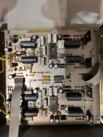
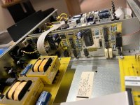
hey, not long ago I acquired a dac from the 90s called the muse model two. it uses pcm63p-k grade chips, a cs8412 input receiver, df1700 digital filter and ad846 op amps.
I want to upgrade this thing, I want to switch the cs8412 in favor of a wm8804 which should be easy with a wm8804->cs8412 adapter such as fetaudio's offering.
but what should I do with the op amps? is there any upgrades that can be done? I read somewhere that the ad846 is used as a passive I/V. what does that mean? It could be wrong, but there are no schematics to verify that.
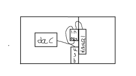
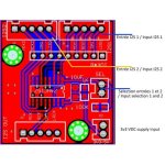
(side question: is it possible that the dac board uses all 16 pins of the IDC cable that is connected from the digital input section? eventually I want to drive the D/A board with a amanero usb and a 12s input switch so that I could keep the current digital input section AND have a separate usb input that I could just switch between. problem is that the only ones I have seen use a 5pin input (I uploaded the picture of the module), will it work? I used my amazing drawing skills to draw an illustration)
I am pretty ignorant when it comes to audio engineering, so a lot of what I said is probably wrong. so any help regarding this would be very much appreciated!
(other dac upgrade or alternatives to what I said are welcome!)
I want to upgrade this thing, I want to switch the cs8412 in favor of a wm8804 which should be easy with a wm8804->cs8412 adapter such as fetaudio's offering.
but what should I do with the op amps? is there any upgrades that can be done? I read somewhere that the ad846 is used as a passive I/V. what does that mean? It could be wrong, but there are no schematics to verify that.
(side question: is it possible that the dac board uses all 16 pins of the IDC cable that is connected from the digital input section? eventually I want to drive the D/A board with a amanero usb and a 12s input switch so that I could keep the current digital input section AND have a separate usb input that I could just switch between. problem is that the only ones I have seen use a 5pin input (I uploaded the picture of the module), will it work? I used my amazing drawing skills to draw an illustration)
I am pretty ignorant when it comes to audio engineering, so a lot of what I said is probably wrong. so any help regarding this would be very much appreciated!
(other dac upgrade or alternatives to what I said are welcome!)
Attachments
-
 WhatsApp Image 2024-09-15 at 19.35.08 (1).jpeg275.9 KB · Views: 257
 -
 WhatsApp Image 2024-09-15 at 19.35.08.jpeg247.3 KB · Views: 194
 -
 WhatsApp Image 2024-09-15 at 19.35.07 (1).jpeg200.5 KB · Views: 166
 -
 WhatsApp Image 2024-09-15 at 19.35.07.jpeg197.2 KB · Views: 168
 -
 WhatsApp Image 2024-09-15 at 19.35.08 (2).jpeg319.6 KB · Views: 172
 -
 muse model two.png6.1 KB · Views: 168
 -
 two-way-audio-i2s-two-i2s-inout-one-out-switching-module (2).jpg49.2 KB · Views: 179
Last edited:
Welcome to diyAudio 🙂
I'm going to move this to Digital Line Level forum as this is really just for intros...
I'm going to move this to Digital Line Level forum as this is really just for intros...

The DACs use 5V logic and your circuit is 3.3V. Also, the DACs don't understand I2S.
I thought so, I got confused, I am thinking about getting rid of the existing PCM board and replacing it with amanero combo 384se and iancanada I2S to PCM converter and connect it to the D/A board. could you tell me if this will work? (also, the d/a board have a separate power supply)
Last edited:
this is amanero I2S output and input connections

this is the I2S input for the iancanada I2S to pcm converter and how to connect it to the pcm63.

this is the I2S input for the iancanada I2S to pcm converter and how to connect it to the pcm63.
and addressing the 3.3v logic circuit, based on iancanada all these dac chips were tested with this I2S to PCM board. he writes: "The logic level of all output signals of this I2 S to PCM board is 3.3V LVTTL. Though all of 5V DACs we tested allow LVTTL levels on their digital inputs, you have to make sure yours too: in your DAC data sheet check if digital input VIH (High) minimum level is +2.0V".
the PCM63 VIH is 2.7V.
the PCM63 VIH is 2.7V.
I read somewhere that the ad846 is used as a passive I/V. what does that mean?
I think it means that the AD846 is being used as a buffer stage after the I/V resistor which is directly connected to the DAC's current output. If so I rather think that's not an ideal application of an AD846 as when its working as a buffer its rather noisy, at least in comparison with the output noise of the PCM63. You could get lower noise (though inferior dynamic performance) by swapping in (say) an OPA627. Whether that lower noise propagates through to the outputs though will depend on how the anti-imaging filter's been implemented. As you say, we don't have schematics.
According to this review - http://www.soundstagenetwork.com/revequip/duvall02.htm there's a 4th order Bessel reconstruction filter after the I/V buffer.
Yes, I know all that. I was responding to your initial post which suggested you wanted to insert your 3.3V PCB into an existing 5V circuit to select between two inputs.and addressing the 3.3v logic circuit, based on iancanada all these dac chips were tested with this I2S to PCM board. he writes: "The logic level of all output signals of this I2 S to PCM board is 3.3V LVTTL. Though all of 5V DACs we tested allow LVTTL levels on their digital inputs, you have to make sure yours too: in your DAC data sheet check if digital input VIH (High) minimum level is +2.0V".
the PCM63 VIH is 2.7V.
If you already have all the answers, why are we here?
because I am not sure how to make this all happen, for example where do I find a power supply to power the I2S to PCM converter? it says that it needs a 4-6v with a maximum current of 50mA. where do I find such a power supply?!
Why do you need an I2S to PCM converter? It's an additional PCB, power supply, connectors, and wire, all adding noise and jitter for no purpose.
because as the gentleman above stated, the pcm63 cannon be used with I2S, the amanero usb output I2S.
Why do you need the amanero? If you are going to use the Muse you should use something that can talk to it directly, without having to hack it. There are plenty of USB DIRs that output S/PDIF, which is something the Muse can understand.
can you recommend me some?, also, I don't need it to output s/pdif I need PCM out. (master clock, bit clock, world clock and serial data)
Last edited:
OK, I'll defer to your expertise. But, I curious, what are you going to do with master clock, bit clock, word clock, and serial data? I didn't know the Muse had those signals broken out on a connector of some kind.
those are just what the digital board sends to the pcm63 since it is only data language it can read. for a dac to work it needs these values to create a line out in the end. PCM and I2S are NOT input connections. (there is some dacs that have I2S inputs, this is to bypass the input receiver, what an input receiver does is convert digital in's such as coaxial spdif and break them down into data. so a I2S input's purpose is to bypass the input receiver, and connect directly to the dac.)
@EitanDainn have you decided whether to keep the DF1700 or not? If you're keeping it, it would be a good idea to check its datasheet as it doesn't accept I2S from my reading of that. It does though create what you're calling 'PCM' so you won't need an additional board to create that if you're keeping the DF1700.
@abraxalito, I intend to either just upgrade the current board with a better input reciever (i.e wm8804 or dir9001) or go overboard and say goodbye to the old digital board all together and introduce a new modern solution. (i.e the talk about the I2S to PCM converter and amanero usb interface with spdif in)
this is just an old board, old dacs are known to age when it comes to the timing and data converting realm. thankfully the D/A board of the dac is pretty timeless and uses high quality parts.
Hi, just stumbled on this and I have a comment.I think it means that the AD846 is being used as a buffer stage after the I/V resistor which is directly connected to the DAC's current output.
There is another possibility, and I think it's more likely: that they used the AD846 in the smart way. Similar to what is shown here: https://www.diyaudio.com/community/threads/using-the-ad844-as-an-i-v.227677/
(Used as a current conveyor. It is still considered passive I/V conversion.)
- Home
- Source & Line
- Digital Line Level
- need help with a 90's DAC (Muse Model Two)