Hello everyone i am just a newbie both for this forum and for DIY electronics. My experience is limited to soldering guitar cables and building one amp for home which I found the diagram from a random website. It was just do whatever you see and do not question things kind of experience.
Normally I build lots of acoustic instruments but this time I want to build something different for myself so i builded multiscale ashbory style bass. It is the first electric instrument that I built. For this little and weird instrument now I want to build a little and weird practice amp.
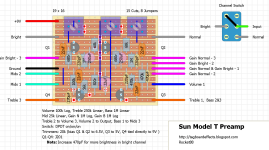
My main idea is modify the diagram of the model t preamp diagram and turn it into a practice amp. But with my lack of knowledge (maybe ignorance) I could not figure out how I could modify this diagram and build the final product.
The challenges for this project:
The amp will drive the 4ohm 3W exciter,
It should be suitable for bass guitar and
I want to use saturable reactors as a gain component.
Basically i do not know how to set the output for 4ohm 3W. I know I need to select input and output capacitors a little bigger for making it bass guitar friendly but is there anything else that I need to tweek? Last but not least is it a stupid idea to try to create an amp based on a preamp circuit?
I shared the diagram for the Sunn Model T preamp that I want to modify. I will be so glad if someone can help me with this project.
Best Regards
Normally I build lots of acoustic instruments but this time I want to build something different for myself so i builded multiscale ashbory style bass. It is the first electric instrument that I built. For this little and weird instrument now I want to build a little and weird practice amp.
My main idea is modify the diagram of the model t preamp diagram and turn it into a practice amp. But with my lack of knowledge (maybe ignorance) I could not figure out how I could modify this diagram and build the final product.
The challenges for this project:
The amp will drive the 4ohm 3W exciter,
It should be suitable for bass guitar and
I want to use saturable reactors as a gain component.
Basically i do not know how to set the output for 4ohm 3W. I know I need to select input and output capacitors a little bigger for making it bass guitar friendly but is there anything else that I need to tweek? Last but not least is it a stupid idea to try to create an amp based on a preamp circuit?
I shared the diagram for the Sunn Model T preamp that I want to modify. I will be so glad if someone can help me with this project.
Best Regards
Attachments


The active devices (tubes, transistors) are restricted in what they can do.
Some are more suitable for a preamp. Some are more suitable for a power amp.
Even the topology itself (how the parts are connected together) can be more suited to a preamp or power amp.
Start with the speaker that you want to use, and its drive requirements.
You can begin the design with a blank sheet of paper (if you have the experience and knowledge),
or else with a known circuit that closely approximates what you need (if you don't have the knowledge).
But that preamp is not close enough to a useful circuit to start with, for driving your speaker.
Maybe you could start with a Sunn amplifier instead, but it would probably have much more output than 3W.
You might want to go have a look at Rod Elliott's web site for inspiration, he has some great pre and power amp circuits to look at and modify to suit your needs, he can be found at https://www.sound-au.com/
🐭
🐭
Thank you very much for you all. Thanks to you i understand, i was asking for impossible. Finnaly I bought some basic components and trying to breadboarding my bass amp designs with the new knowladge.
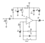
I made my first design with what i understand from other circuit diagrams.
I have found lots of JRC4558, I heard they not so good for audio but I have a lot of them right now so I wanted to use them.
For speakers I have 2 cheap speaker exciters (3W 4 ohm each) which I am planning to use both in the same panel.
Last but not least, if the circuit can work with a 9 volt battery it would be perfect.
Now I can not calculate the component values for driving the exciters. I don't know how to calculate the output wattage. As far as understand i need 6W for output. I could not find a dual opamp in LTspice so I drew 2 op amps in series.
If you can help me with reality check again i would appreciate it.
Still the same basic problem, a 4558 can't drive a 4 ohm speaker driver.
You can possibly try a many-in-parallel opamp solution but not sure that's a good idea for a 1st project.
Do you have anything in your parts drawer that might be an alternate solution? Either some kind of power transistor, or maybe one of those ubiquitous 100 ohm paper tweeters?
You can possibly try a many-in-parallel opamp solution but not sure that's a good idea for a 1st project.
Do you have anything in your parts drawer that might be an alternate solution? Either some kind of power transistor, or maybe one of those ubiquitous 100 ohm paper tweeters?
i have lots of voltage tranformers if they are relevant. i can salvage some power transistors from old laptop adapters or led bulb drivers or some old car electronics. Also i have some pnp and npn transistors like A42 or A92 or 2n5401 etc...
I can try to add preamp stage and AB class power stage to this i guess
I can try to add preamp stage and AB class power stage to this i guess

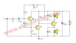
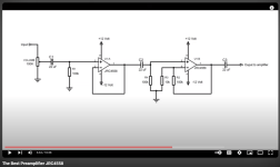
After I searched a bit more I found some circuits that I think I can use as reference, then I tried to put them together. Only addition that I made is a low pass filter at the second stage of the preamp to cut above16kHz.
I attached the reference circuits also in case I made a mistake while trying to redraw them.
What do you think? Can this idea go somewhere usefull?
Thank you again
Kind regards
Attachments
The quickest and easiest way would be for you to investigate the small audio power amplifier ICs like the TDA2030. This IC is capable of 10 - 15 Watts RMS (according to supply voltage) and only needs a handful of other components around it to get it going. I built a small practice amplifier using this IC a while ago. I found a 12" 8Ω loudspeaker on Ebay for about £16, and the other components for the amplifier came to about £8 altogether. The preamplifier part has three op-amp ICs, three band EQ, optional clipping (aka "Fuzz") and a volume control. The whole thing was built into a cube-shaped wooden box, with the controls on top, and I used a little commercially made 60 Watt SMPSU unit to power the whole thing. It's a great little practice amp, and in the hands of my nephew, it's plenty loud enough to annoy his parents!
If you want the circuit details, I can post them here.
If you want the circuit details, I can post them here.
- Home
- Design & Build
- Electronic Design
- Need help while designing my practice amp