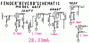
I'm trying to reconcile what I see on datasheets with real world current draw. I was just looking at the Fender 6G15 schematic and shopping for a power transformer. The 6G15 uses one 12AT7, one 7025, and one 6K6. According to the datasheets, these tubes have a max plate current of 10 mA x 2, 1.5 mA x 2, and 37.5 mA in class A, respectively, for a total of 60.5 mA. However, the power transformer has a 306V secondary rated at only 27 mA. Why wouldn't the secondary be spec'd for the total plate dissipation?
I'm not actually planning on building a 6G15. I bought a 6G15 power transformer so I could build a tube preamp. Now, if I base my calculations on the datasheets I will be pushing the limits of the PT, since the 12AU7 and two 12Ax7's I plan to use would draw a total max plate current of 27 mA. Clearly, as I've learned from looking at the 6G15, a real world tube circuit doesn't need all that current. How do I know how much current I really need? What am I missing?
I'm not actually planning on building a 6G15. I bought a 6G15 power transformer so I could build a tube preamp. Now, if I base my calculations on the datasheets I will be pushing the limits of the PT, since the 12AU7 and two 12Ax7's I plan to use would draw a total max plate current of 27 mA. Clearly, as I've learned from looking at the 6G15, a real world tube circuit doesn't need all that current. How do I know how much current I really need? What am I missing?
Those are maximums for each tube - you don't intend to run each at its maximum rating, do you? The transformer may be rated for 27 mA because that's the DC current drain it supplies (a look at the schematic confirms this - i.e. 24 mA in the 6K6). The reverb unit uses a half-wave rectifier, and considerably more current can be obtained from a full-wave bridge (which has better regulation, less ripple as well).
Actual current draw per stage can be found by Ohms law - V/R. If you know the cathode voltage, divide it by cathode resistor value. If you know the plate voltage, it's (supply voltage minus plate voltage) / plate resistor value.
Actual current draw per stage can be found by Ohms law - V/R. If you know the cathode voltage, divide it by cathode resistor value. If you know the plate voltage, it's (supply voltage minus plate voltage) / plate resistor value.
Not so much that there is audio involved.
The Data Sheet values are often Show Off values. The 12AT7 is a TV tuner for VHF work. It can run 10mA to drive low-Z tanks. But in audio we almost NEVER run a 12AT7 (or 12AU7!) anywhere near 10mA. Our loads are not that tough.
The 6G15 demand can be read-off directly from the plan. 27mA, 28.33mA, all the same. Note that all tube-work is +/-20% on voltage and current. So is the "maximum" current of power transformers. 20% over-current on a transformer may shorten its life from 10,000 hours to 5,000 hours; it does not blow-up right away.
So what is YOUR plan? Are you running 12AU7 right AT 10mA? If you have audio-typical 100K plate resistors, you are more near 2mA.
Attachments
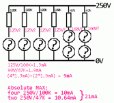
Good info, Tom and PRR. My build will have 4 12ax7 stages with 100k on the plates and a 12au7 cascode at the end. The upper triode of the cascode will have a 47k plate resistor. I'll do some number crunching when I have a few minutes. Meanwhile, am i correct in assuming that the total plate current will be less than 10 mA?
Well, what is the worst that can happen?
You know your resistors but apparently do not know what the tubes will do. Draw it out. Mark the tubes "?", indicating "don't know". Maybe they are dead-short? Probably not, a short is cheaper than a tube, so the tubes probably "do something". But just pretend.
Just from the resistors you cite, you could have 21mA (at 250V supply).
But the "short" assumption is so likely wrong. A closer guess is that the tubes are a "fair fight" with their resistor, and each gets "about half" of the supply voltage. (The cascode is a complication, I have assumed "about 1/3rd".) This suggests 9mA @ 250V.
250 not 295V because you WILL want multiple R-C filter stages (Fender's 10K 40uFd) to get B+ buzz down to phono level.
Attachments
- Status
- Not open for further replies.
- Home
- Amplifiers
- Tubes / Valves
- Need help understanding plate current ratings

