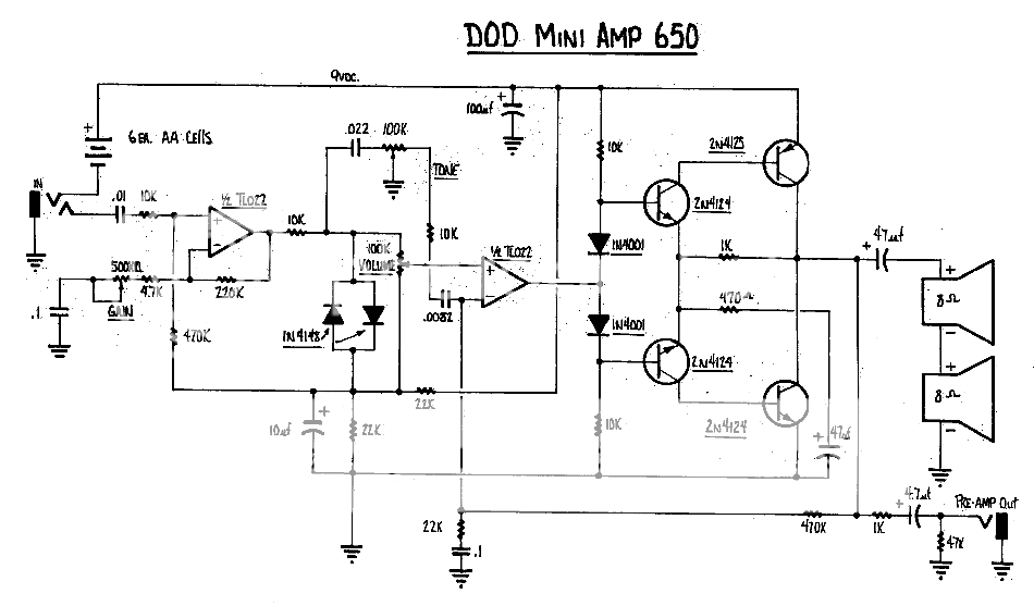
I'm looking at a schematic of a guitar amp that has built in distortion circuit and hoping to extract the amplifier part only so I can combine it with any distortion pedal later. I was going to replace the distortion part around the TL072 with a simple source follower FET buffer. That should work I think...but I'm not sure about the negative feedback loop (470K-22K+0.1uF network) that goes back to the opamp. Can it work with my source follower too? Would it go back to the source? I assume that I'd need to tap the output after the filtering cap, as I wouldn't need DC feedback, just AC, right?

Thanks in advance,
Bane

Thanks in advance,
Bane
If you remove the back to back 1n4148 diodes, the clipper is removed. Each half of the TL072 has its own neg feedback.
TL072 is FET input.
TL072 is FET input.
Thanks. I realize that, but was hoping to get away with a single fet and squeeze the whole circuit on a 1x1" protoboard.
Cheers
Cheers
So is this for a mod of the original amp or for a new project?
The second half of the TL072 complete with AC feedback is integral to the power amp. The circuit also is kinda **** by modern standards (CFP output with gain and no emitter resistors, so dubious idle current stability, no cap across bias diodes, ...), though still much better than an LM386 job. If you really want something as compact as possible, a more modern chip amp may be a better bet for the power stage.
The second half of the TL072 complete with AC feedback is integral to the power amp. The circuit also is kinda **** by modern standards (CFP output with gain and no emitter resistors, so dubious idle current stability, no cap across bias diodes, ...), though still much better than an LM386 job. If you really want something as compact as possible, a more modern chip amp may be a better bet for the power stage.
That´s a quite poor amplifier, has no merit enough to be copied, IF you just want a 9V powered amp to add or test your own distortion or pedals, fine, tbhen just use an LM386.
Will put out about the same or a little more, and to boot be simpler and cheaper.
Just build one and try it.
There is one version with a Fet front end, check the usual pedal sites, I guess it´s the "Ruby" but might be mistaken.
Will put out about the same or a little more, and to boot be simpler and cheaper.
Just build one and try it.
There is one version with a Fet front end, check the usual pedal sites, I guess it´s the "Ruby" but might be mistaken.
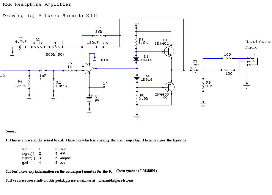
thanks. Yes, I understand that it's less than ideal amp....but was curious to try it out. We like quirky circuits for guitar 🙂 I'm experimenting with converting various radios from 50-60-70s into guitar amps and it's very interesting. Some are germanium, some ge-si mix, some push/pull, some single ended...and all are interesting in their own way. I came across this circuit that is relatively similar and that diode phase inverter piqued my interest...so I wanted to give it a try. There's a similar circuit with a single opamp input. Maybe I can mix them together


You may want to look for a better schematic there, this one appears incomplete and would not work. There's another out there which includes a rail splitter for +in bias and shows the IC to be a TL071. BTW, TL07x performance is generally pathetic at low voltages, and it's not a great output driver. These days I might use OPA1652 or the like. And add a capacitor across the bias diodes, of course.
- Status
- Not open for further replies.
- Home
- Amplifiers
- Solid State
- Need help understanding feedback loop