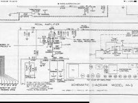
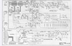
I’ve attached a couple images from a schematic showing -19 and -22 volt bias taps achieved by isolating the center tap from the ground with a 180R resistor. It’s a tad more complex as you’ll see in the schematic. The -19 volt tap is used at the output tubes in a very conventional manner. The other tap is used to cut off a triode and isn’t really pertinent.
I find this circuit incredibly cleaver. I’m wondering why I shouldn’t swipe the idea for a build I have in mind where I’ve got a bit more B+ voltage from the PT than I’d like. My thinking being that the voltage loss across the resistor would also lower the B+. A win-win so to speak.
I also wonder why I’ve not seen this design before? It’s simple, it seems like the bias supply would be reliable enough and the bias voltage would come up at about the same time as the B+. If you can think of some downsides, I’d like to hear of them.
The schematic is from a Hammond organ amp, an AO-29. I post here because the idea is pertinent to a hifi build.
Attachments

Last edited:
The bias voltage will increase as the HT current rises, I think, so it will set the bias point automatically if the largest current load are the main output tubes.
If some auxiliary equipment were plugged into the HT it would upset the bias point, so this limits the circuit's use-cases a bit.
If some auxiliary equipment were plugged into the HT it would upset the bias point, so this limits the circuit's use-cases a bit.
Definitely borrow it with the caveat that you may find that it works much better with zener diodes instead of a big resistor.
Thanks, Merlinb, for the link to that fine article. It’s good to put a name to it. It looks to me like the final circuit in the discussion is the one in the schematic. I’m a just a little bit surprised that this circuit is so obscure. There is so little to it I think I might give it a go.
Yes that’s the point I’m considering now. I would think so in most cases with the possible exception of Class A application with more or less constant B+ current. At issue is a self biased single ended triode pentode amp and I was considering the mod to fixed bias as I would like to be able to swap tube types without changing cathode resistors. The variation in current would create more bias, which might actually work to advantage considering that higher current tubes generally require greater bias. I have mounted amp meters and I envision a nice multi turn bias pot. Something to ponder with a calculator in hand.Definitely borrow it with the caveat that you may find that it works much better with zener diodes instead of a big resistor.
The resistor circuit might be good also in a solid state rectified guitar amp to create sag as the bias would go up with increasing power, thereby emulating the sag of a tube rectifier.
Last edited:
I mean, if you have two cathode resistor values, you can just use a toggle switch to go between them. Often times a single ended pentode amp and a single ended triode amp with the same tube are going to need wildly different circuits and output transformers anyway, so assuming that just adjusting the bias and moving the screen grid connection will let you successfully go from one to the other is rather optimistic.
Back in the 50s you occasionally saw back biasing used where the back biasing resistance was actually the heaters of smaller valves in the set, free-lunch style.
I see my description of the amp was muddled a bit. I had intended to say triode connected pentode (or heptode). Point being screen grids are not an issue. But yes, I agree about switching cathode resistance. I used two in series with a switch to shunt one for a time and it worked quite well. Once the ammeters were added however, it just seemed to beg for better control.I mean, if you have two cathode resistor values, you can just use a toggle switch to go between them. Often times a single ended pentode amp and a single ended triode amp with the same tube are going to need wildly different circuits and output transformers anyway, so assuming that just adjusting the bias and moving the screen grid connection will let you successfully go from one to the other is rather optimistic.
I used a junk box salvaged transformer to make a fixed bias supply and was quite satisfied with that. But I learned that the tubes that I thought sounded best, some old KT88s couldn’t be biased. They were too gassy for fixed bias operation but ran quite well and on OP with the cathode bias. Not to surprising as they were pulls from a fixed bias PP amp. Yet another argument for cathode bias.
Yeah, why not? Free lunch, like the many examples of 6V6 and EL84 amps using small signal tube heaters as cathode bias in the phono stage.Back in the 50s you occasionally saw back biasing used where the back biasing resistance was actually the heaters of smaller valves in the set, free-lunch style.
By the way, I like your valve wizard website. Lots of good information there!
Last edited:
Back in the 50s you occasionally saw back biasing used ...heaters of smaller valves....
Also a field coil.
It is more synergistic in a RADIO. A line-up of tuner tubes may suck as much current as a small power pentode. But their current does not try to vary with audio signal as tends to happen in a power stage. (Instead, with AVC, it varies with RF/IF gain..... but some radios had little AVC.)
- Home
- Amplifiers
- Tubes / Valves
- Need help understanding bias supply in power supply circuit