The slightly different zener voltages will impact the adjustment range all other things being equal.
I don't think Q401 and 402 will have suffered any damage. With the 1k5 open the output voltage would shift to a positive value close to the rail voltage. That would reverse bias Q402 base/emitter junction via the 22k feedback resistor and it would self limit (non destructive breakdown) at around 8 volts or so across the junction. The 22k is severely limiting the current and stopping anything bad happening.
If you simply hold a finger on either of those transistors you will see a shift in offset as the pair unbalances due to the thermal difference.
The very slight difference in Vbe can be accounted for by the fact that there is a small offset, but it doesn't follow that the devices are at fault in causing that offset.
The BC640 is an 80 volt device, and I can see won't be happy until you have swapped them as a test 🙂 Try it.
HelloQ404 is attached to the main heat sink or in the PCB?
Q404 is on the PCB, solder side. It is in the air flow of the power transistors. (which are as cold as they can get, being at the room temperature (checked) )
Uh, que cagada. Q404 would be good that be in the heatsink as it is the thermal pick up pf the power transistors. In any case, make a simple test. Put the amplifier in conditions to measure idle collector current of the output devices, when cold. Then apply heat from a hair dresser or heat gun to the output heatsink, to get, a thermal increase of say, 15-20°C. The collector current MUST decrease notably if the amplifier is workin' properly. Use no load, no signal, and the lamp in the fuse holder.
So, you will check that in case of a thermal overload (as in the case of large continuous output or a warm day), the amplifier continues thermally stable.
So, you will check that in case of a thermal overload (as in the case of large continuous output or a warm day), the amplifier continues thermally stable.
 one for tomorrow.
Just take it slow and double check the pin outs of your replacements if you want to try those.
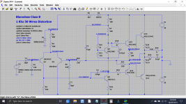
I've just done a quick hatchet job on Doug Selfs amplifier which is actually very similar in outline to yours. This shows the voltages in a simulation and curiously the offset is not quite zero even when the preset is turned all the way down.
Just a bit of fun trying this 🙂
Attachments
Good luck. I'm away from internet (Unplugged) all the weekend. Until Monday.
Have fun 🙂 I'm through for today anyway.
Hello,
Being at the swap of the two TO92 transistors, do you think it would be wise to stick the Q404 on the heathsink ? (it is also a TO92) I can glue it using silicon conductive compound and wire it to the PCB ? On the other hand, Luxman had done it this way in the whole line of like amps, and nobody complained about thermal stability problems .... It is not perfect but may be effective.
If the swap is unsuccessful I think I've found a replacement : KSA992FBU TO92, matching specs and pin-out, available at Farnell's so not a fake ....What do you think of it ?
Have a nice day !
Last edited:
I wouldn't alter the physical position of Q4 without first seeing if it doesn't work correctly as designed.
Yes, I agree it would normally be on the heatsink to track thermal changes but there may be reasons for it being as it is. For example the 50 milliamps recommeded bias is actually theoretically to low for that configuration and component values (its around 60% of where it should be) but that will be done for practical reasons (such as limiting heat dissipation).
The bias will drift with temperature. What you don't want is for the bias to increase uncontrollably (thermal runaway) as temperatures rise. If you play the amp loud and get it hot then the bias should not go over (lets say) 70 or 80 milliamp and it should fall fairly quickly once you turn the volume down. It may fall below the set 50ma as it re-stabilises thermally but that's fine.
The KSA992 sounds OK
KSA992
Did not had a second to work on this poor amp. Too much chores to attend.
Home Sunday will be quieter !
Home Sunday will be quieter !
Hello !
So I removed the two Q401 and Q402 transistors.
While I where at it, I tested them using the Chinese transistor tester, clone of the Microkontroler.net design.
Results are as follow
Q401 ß = 422 Uf = 655 mV
Q402 ß = 149 Uf = 638 mV.
Definitely not paired....
I then soldered them back after swapping.
Result is very bad. I can't set the output voltage below 83.1 mV (worst being 141,0 mV)
as I was getting 25 mV with the transistors in their original position, the swap is .... not successful ....
So I'm left with :
1) swap them back and leave the amp as it is.
2) buy a handful of KSA992, find two of them close in gain and Uf and put them in place
3) buy another working amp ;-)
What should I do ?
Oh, and by the way, on the schematic, some resistors are flagged "Flame proof type" (actually "Fleme" ). What does that mean and what kind of resistors are flame proof ?
Thanks for your help and have a nice Sunday !
Flame proof... ordinary carbon or metal film resistors when overloaded tend to both smoke (a lot) and smell (a lot) and that frightens customers should they see clouds of smoke and smell burning coming out of the unit. So the manufacturer fit 'flame proof' which fail without drama when overloaded. There are also similar parts called 'safety resistors' that can be used in place of fuses and that fail safely open circuit when overloaded. Philips used to love using these parts 🙂
Having a selection of transistors to match is one way to get a better result, however it still may not be quite as you expect because the circuit itself isn't properly balanced. Ideally you want a pair of transistors to give no offset when the preset is in the middle. Why in the middle? Because that is in the centre of the range of adjustment that the manufacturer designed into the amp.
The ideal match to give no offset under those conditions will almost certainly not be a pair of devices that match electrically. Many amplifier are designed with DC precision in mind these days... this is not one of them 😉
In the simulation of the amp, if the preset is centred and matched devices used (and they are 100% matched because the simulation model of the part is the same) then the offset is over 100 millivolts.
The 25mv offset (even 80mv) isn't going to cause any issues.
You could always alter that resistor in series with the preset to give you a tiny bit more adjustment range if you really want to see 0.00 offset. Or you could try a slightly different zener voltage or 😱 you could also remove the other channels transistors and try and get a better match using all four devices to play with.
Flame proof... ordinary carbon or metal film resistors when overloaded tend to both smoke (a lot) and smell (a lot) and that frightens customers should they see clouds of smoke and smell burning coming out of the unit.
I bet this has nothing to compare from a smoking selenium rectifier or an aging Gmov smoking....
A co-worker once saw a Gmov smoke on a computer power supply. She was so affraid that she went home and refused to come back for the day !
Regarding the Luxman and the input transistors, I'll swap them back and leave the amplifier live its time amplifying music !
Thanks a lot for your help.
So fate has it. I'll change the 2SA942 transistors. While reinserting one, I snapped the emitter wire flush with the case. Damned !
I think this beast enjoys having it's innards exposed !
I think this beast enjoys having it's innards exposed !
Thanks, Karl. Yes, at home I have no cellular, nor tablet, nor internet. Neither a TV!Have fun 🙂 I'm through for today anyway.
Only music and AM radio.
Hello !
Got the Fairchild transistors.
Tested them. I have 3 lots : one has around 350 gain, the other one 390 and the last one and less numerous 430.
I can get two transistors with ß=430 and Uf 640. I did not try to find a couple in the lot with ß = 390 ...
So are the two I selected suitable ? Do I need to find 4 of them in order to install two on the other channel ?
What do you think ?
Have a bright day !
The absolute value, is of no importance. Use the higher available, and in any case,the best matched between them.
- Home
- Amplifiers
- Solid State
- Need help to fix a Luxman L-3 faulty