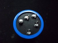
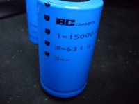
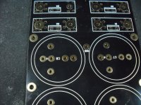
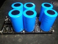
I'm trying to fit these BC Components caps onto BrianGT's PSU board but the 'pinout' on the caps are... well, weird. Not a single pin fit a single hole on the PCB. Any suggestions?
Oh, and is only pin 5 negative and the rest positive?
Oh, and is only pin 5 negative and the rest positive?
Attachments
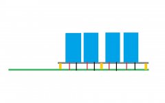
If you don't want to re-drill the PCB, then you will have to fit the caps remotely.
Easiest way is to mount the caps on a standalone platform above the PCB and just connect +VE and -VE to the PCB using heavy gauge wire.
Even tidier to mount the caps with the pind pointing down and just make short legs to meet the holes.
Easiest way is to mount the caps on a standalone platform above the PCB and just connect +VE and -VE to the PCB using heavy gauge wire.
Even tidier to mount the caps with the pind pointing down and just make short legs to meet the holes.
Attachments
Last edited:
Check with a DMM to see if any of the other pins are connected to Pins 1 or 5.
Okay, I checked using the continuity function and between pin 1 and pin 5 there's something going on, but absolutely nothing between any other pin. That should mean pin 2-4 are for support only, right?
But what about the PCB, should I drill holes for the supporting pins (and the live ones for that matter) or should I cut them off?
If the pins 1 and 5 fit the holes on the board then you can just cut off the others.
I would make a little rubber (or similar) cushion to both make sure that nothing remaining of the pins touches the board and gives the cap a solid base to sit on so that it cant move.
That's a very good idea, thanks for the help.

- Status
- This old topic is closed. If you want to reopen this topic, contact a moderator using the "Report Post" button.
- Home
- Amplifiers
- Power Supplies
- Need help to fit caps on PCB